

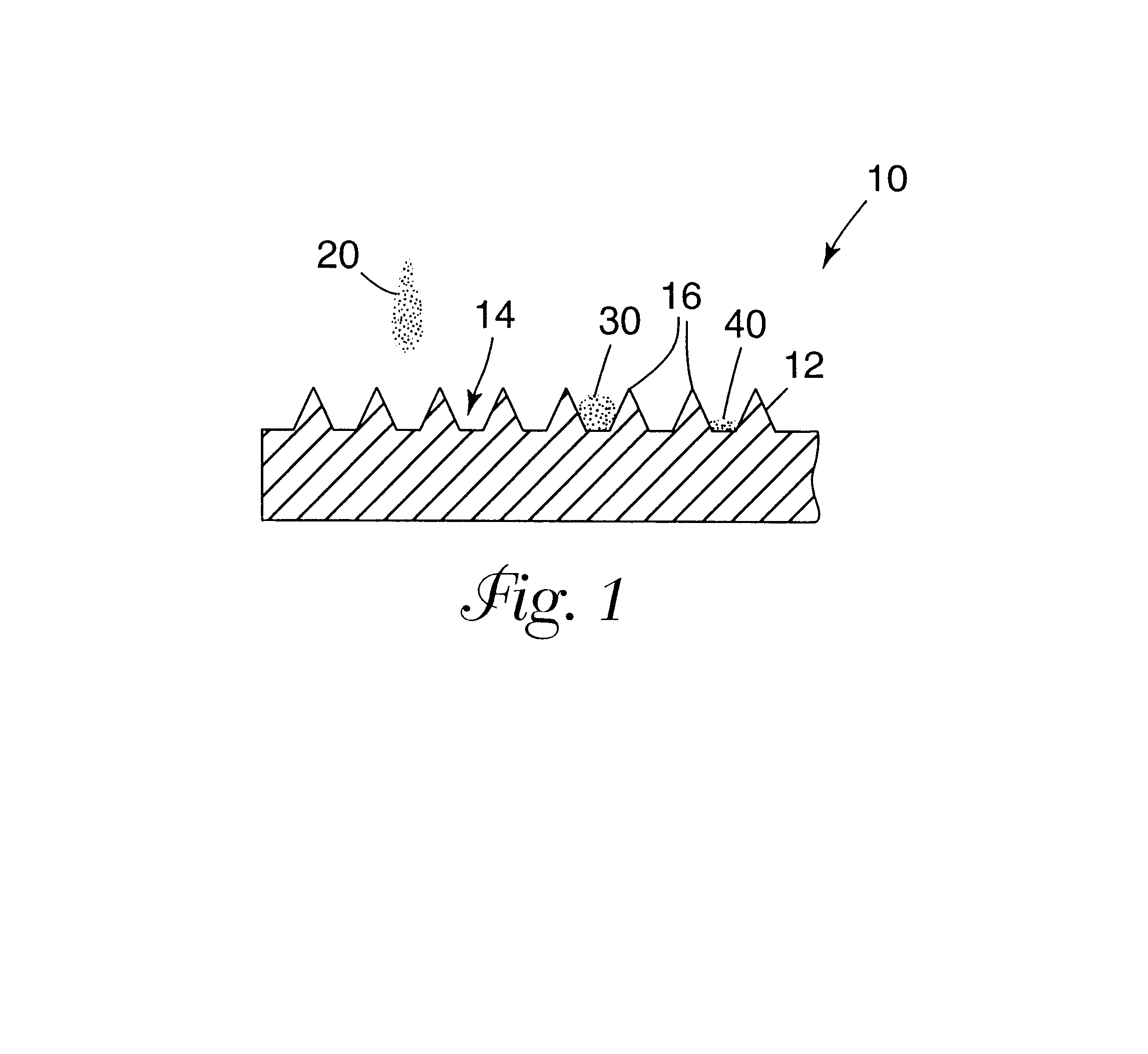
Optically transmissive microembossed receptor media
- Summary
- Abstract
- Description
- Claims
- Application Information
AI Technical Summary
Benefits of technology
Problems solved by technology
Method used
Image

Examples
example 1
Generation of Substrates and Gardner Haze
In this example, large features are shown to provide acceptable Gardner Haze in an image projected by an overhead projector. Gardner Haze is measured for all examples using a Gardner Hazemeter from BYK-Gardner Company (Columbia, Md. and D-82534 Geretsried, Germany), using ASTM D1003-97 "Standard Test Method for Haze and Luminous Transmittance of Transparent Plastics", the disclosure of which is incorporated herein by reference.
Four topographies were generated on polyimide film (DuPont of Wilmington, Del.) by laser ablation. All patterns comprised inverse images of closely packed square cavities having a height (H); wall thickness at the wall top (B); an angle (A) of wall to a plane perpendicular to the plane of the sheet; and pitch (P) or center-to-center distance between adjoining cavities. The polyimide film was used in compression molding of polycarbonate film (General Electric, Fairfield, Conn.) such that replication is essentially comple...
example 2
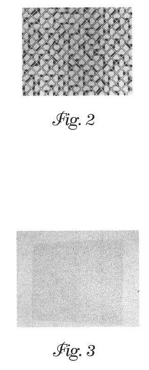
Effect of Mastering Method on Haze Performance
The amount of haze resulting from the light scattered from the microembossed receptor surface is minimized by controlling certain aspects of the design, for example, by requiring steep wall angles and close to zero radius (sharp) corners. The machining method chosen to fabricate a microembossed surface can ultimately have an effect on transparency film performance parameters, such as haze. The minimum corner radius achievable using one machining method may be much larger than that attainable using another. If a given mastering technique cannot produce corners with radii less than a few micrometers, there is likely to be a significant amount of light refracted from these corners in undesired directions. The cumulative effect of this extraneous refracted light over a relatively large area of microembossed surface could contribute to an increased percent haze over that from another film that is identical to the first in all respects except ...
example 3
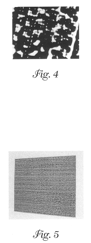
Coalescence Control in Projected Images--Hydrophobic Surface
In this experiment, we will show how coalesced inks on surfaces still provide uniform projected images when the surface to be printed comprises patterns of the current invention.
Transparent poly(vinyl chloride) (Scotchcal.TM. Translucent Film, available from Minnesota Mining and Manufacturing Company) was microembossed with the 100 LPI pattern and was printed upon by an HP 890C ink jet printer in "plain paper" mode, "Econofast" speed. The result was a very uniform appearing image, compared to the blotchy image obtained with even a normal ink jet receptor film, such as CG3460 (obtained from Minnesota Mining and Manufacturing Company) or Hewlett-Packard Corporation's "Rapid-Dry" Inkjet Transparency sheets (obtained from the Hewlett-Packard Corporation). However, the image on the microembossed film was of low density because the ink beads up in the corners of the cavities on the low energy poly(vinyl chloride) surface. Microgr...
PUM
| Property | Measurement | Unit |
|---|---|---|
| Volume | aaaaa | aaaaa |
| Volume | aaaaa | aaaaa |
| Volume | aaaaa | aaaaa |
Abstract
Description
Claims
Application Information