Vacuum processing apparatus and semiconductor manufacturing line using the same

a vacuum processing and manufacturing line technology, applied in the field of vacuum processing equipment, can solve the problems of large installation area of the whole apparatus, large installation large maintenance area of the vacuum processing apparatus, so as to suppress any increase in manufacturing cost, improve maintainability, and reduce the effect of productivity of the semiconductor manufacturing lin

Inactive Publication Date: 2003-02-25
HITACHI LTD
View PDF41 Cites 5 Cited by
  • Summary
  • Abstract
  • Description
  • Claims
  • Application Information

AI Technical Summary

Benefits of technology

Therefore, in spite of a larger diameter sample, the number of vacuum processing apparatuses installed in a clean room, having the same area as a conventional clean room, does not need to be reduced. Accordingly, the productivity of the semiconductor manufacturing line does not decrease. Thus, it is possible to provide a vacuum processing apparatus which can cope with a larger diameter sample and, at the same time, can suppress any increase in the manufacturing cost, and has better maintainability.
Further, by employing the vacuum processing apparatus according to the present invention in a semiconductor manufacturing line, it is possible to provide a semiconductor manufacturing line which can cope with a larger diameter sample while keeping manufacturing cost to a minimum by keeping the necessary number of vacuum processing apparatuses, through more economical use of space and, at the same time, without decreasing the maintainability.

Problems solved by technology

In these apparatuses, there is a problem in that the required installation area of the whole apparatus is large since the rotating angles of the transfer arms of the atmospheric transfer robot and the vacuum transfer robot are large.
On the other hand, the processing chamber in the vacuum processing block and the vacuum pump and other various kinds of piping components of the vacuum processing apparatus require maintenance, such as scheduled and unscheduled inspection or repairing.
In the conventional vacuum processing apparatus, there is a problem in that the installation area is large even though the sample to be handled has a diameter d smaller than 8 inches (nearly 200 mm) and the outer size of the cassette C.sub.w, is nearly 250 mm.
An increase in the size of a vacuum processing apparatus due to an increase in diameter of a sample to be processed results in an increase in the required installation area of the clean room, which further increases the construction cost of the clean room, which by its nature already has a high construction cost.
A reduction in the total number of the vacuum processing apparatuses in the clean room having the same area decreases the productivity of the semiconductor manufacturing line and increases the manufacturing cost of the semiconductor devices as an inevitable consequence.
On the other hand, a decrease in the spacing between the vacuum processing apparatuses decreases the maintainability of the vacuum processing apparatus due to lack of maintenance space for inspection and repair.

Method used


Image

  • Vacuum processing apparatus and semiconductor manufacturing line using the same
  • Vacuum processing apparatus and semiconductor manufacturing line using the same
  • Vacuum processing apparatus and semiconductor manufacturing line using the same

Examples


Embodiment Construction

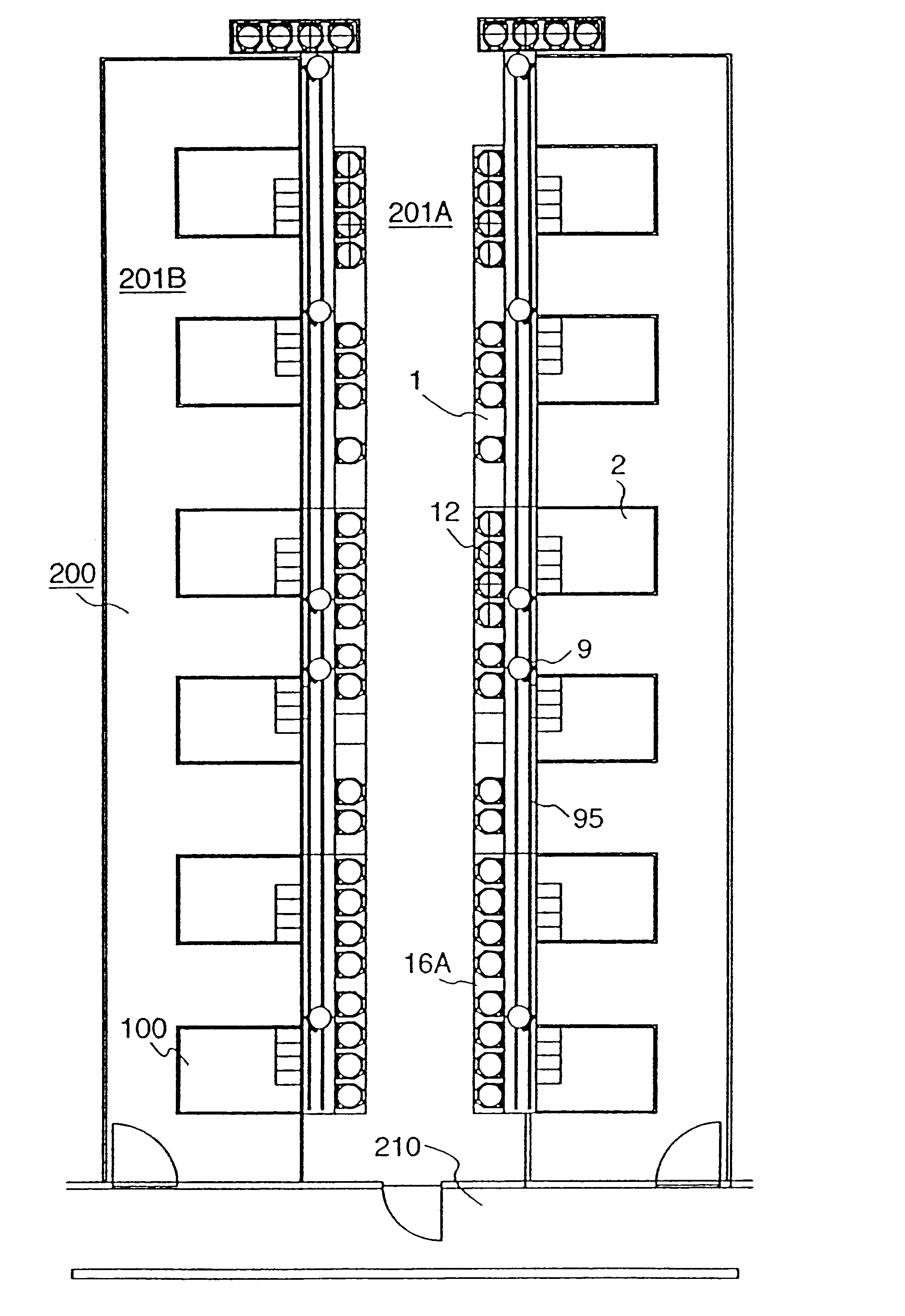
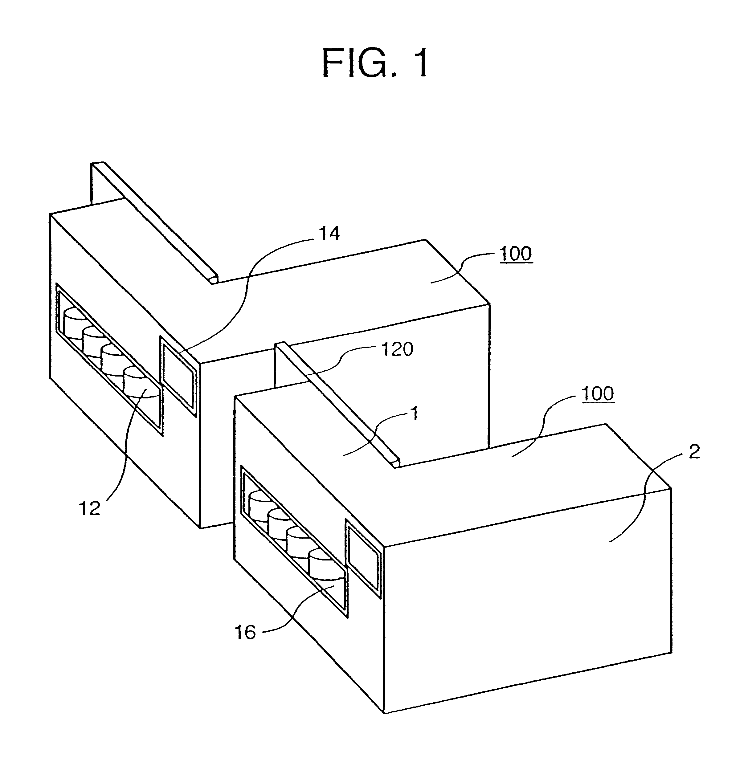
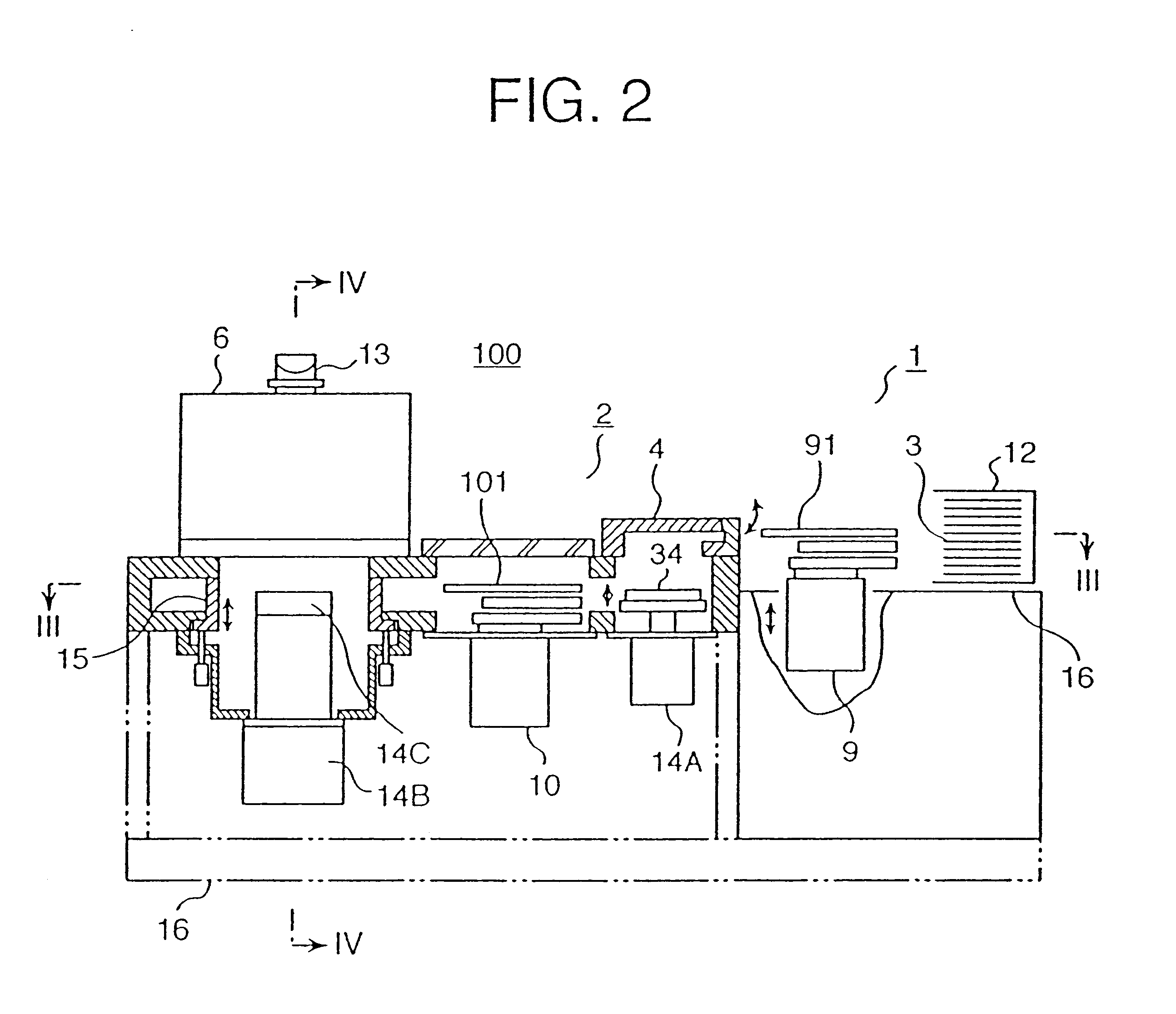
An embodiment of a vacuum processing apparatus in accordance with the present invention will be described in detail below, referring to FIG. 1 to FIG. 4. As shown in FIG. 1, each of a pair of vacuum processing apparatuses 100 is composed of a rectangular block shaped cassette block 1 and a rectangular block shaped vacuum processing block 2. Each of the plan shapes of the cassette block 1 and the vacuum processing block 2 is rectangular, and the whole plan shape formed by both is L-shaped. The cassette block 1 faces a bay path of a semiconductor manufacturing line and extends in the lateral direction of the bay path, and in the front side of the cassette block there are a cassette table 16 for receiving and transferring a cassette 12 containing a sample from and to the bay path and an operation panel 14. The vacuum processing block 2 installed in the back side of the cassette block 1 extends in the direction perpendicular to the cassette block 1 and contains various kinds of devices ...


PUM


Abstract

A vacuum processing apparatus is composed of a cassette block and a vacuum processing block. The cassette block has a cassette table for mounting a plurality of cassettes containing a sample and an atmospheric transfer means. The vacuum processing block has a plurality of processing chambers for performing vacuum processing to the sample and a vacuum transfer means for transferring the sample. Both of the plan views of the cassette block and the vacuum processing block are nearly rectangular, and the width of the cassette block is designed larger than the width of the vacuum processing block, and the plan view of the vacuum processing apparatus is formed in an L-shape or a T-shape.

Description

BACKGROUND OF THE INVENTIONThe present invention relates to a vacuum processing apparatus; and more particularly, the invention relates to a vacuum processing apparatus which is suitable for performing treatment, such as etching, chemical vapor deposition (CVD), spattering, ashing, rinsing or the like, on a sample of a semiconductor substrate, such as a Si substrate, and to a semiconductor manufacturing line for manufacturing semiconductor devices using the vacuum processing apparatus.Basically, a vacuum processing apparatus is composed of a cassette block and a vacuum processing block. The cassette block has a front facing the bay path of the semiconductor manufacturing line and extending toward the longitudinal direction of the semiconductor manufacturing line, an alignment unit for aligning the orientation of a cassette for a sample or the orientation of a sample, and a robot operating under an atmospheric pressure environment. The vacuum block has a load lock chamber in the load...

Claims


Application Information

Patent Timeline
Patent Type & Authority Patents(United States)
IPC IPC(8): H01L21/67H01L21/00H01L21/677H01L21/302B65G49/07H01L21/02H01L21/203H01L21/205H01L21/3065
CPCH01L21/67161H01L21/67167H01L21/67173H01L21/6719H01L21/67196H01L21/67778H01L21/67727Y10S414/14Y10S134/902Y10S414/137Y10S414/135Y10S414/139Y10T70/5805Y10T70/5801
Inventor SORAOKA, MINORUYOSHIOKA, KENKAWASAKI, YOSHINAO
Owner HITACHI LTD
Why Eureka
Try Eureka