Process for making constrained filament niobium-based superconductor composite

a superconductor and filament niobium technology, applied in the field of fabrication of a15 conductors, can solve the problems of nb loss, method obsolete, and time for infiltration should be very shor

Inactive Publication Date: 2003-04-08
COMPOSITE MATERIALS TECH
View PDF20 Cites 14 Cited by
  • Summary
  • Abstract
  • Description
  • Claims
  • Application Information

AI Technical Summary

Benefits of technology

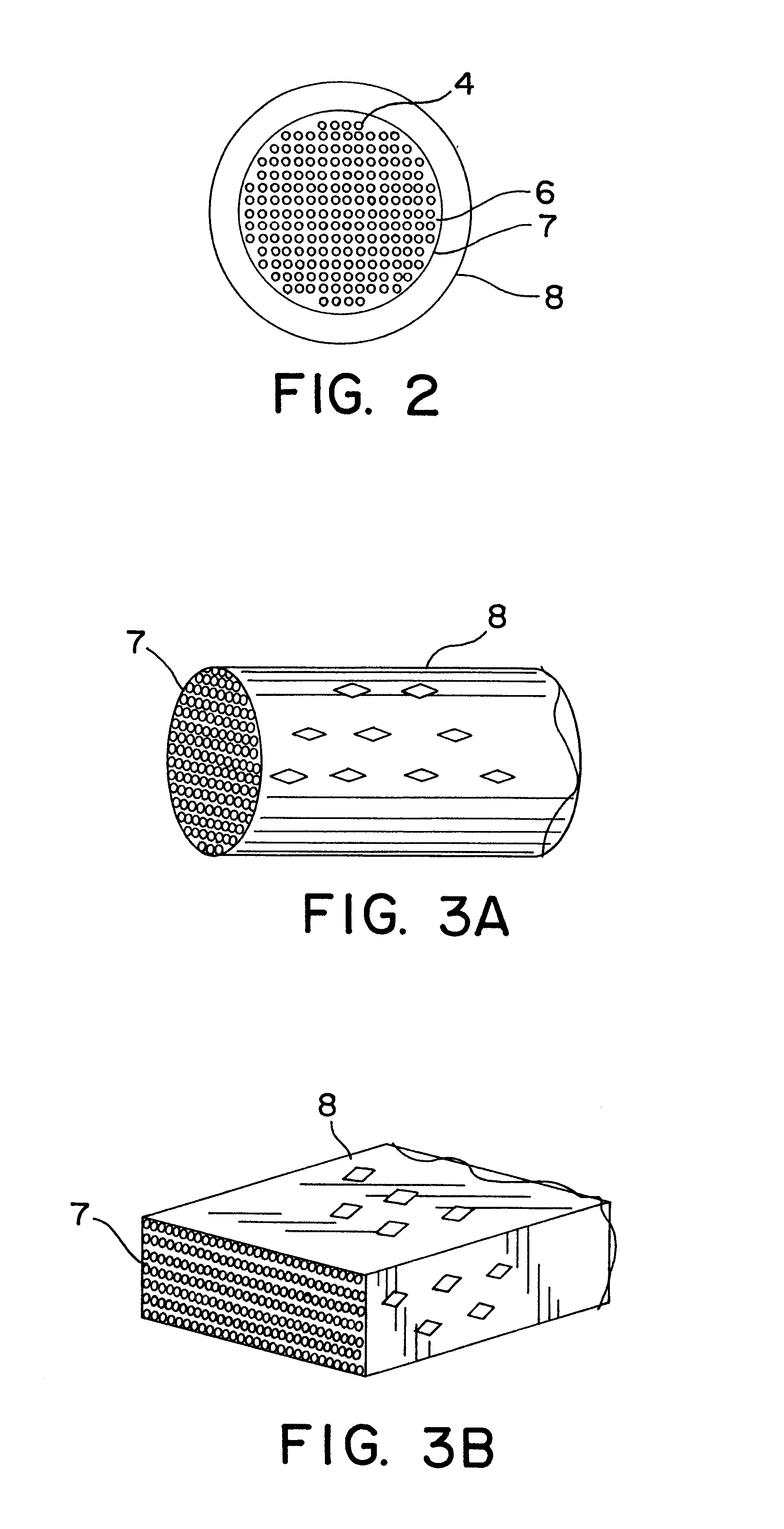
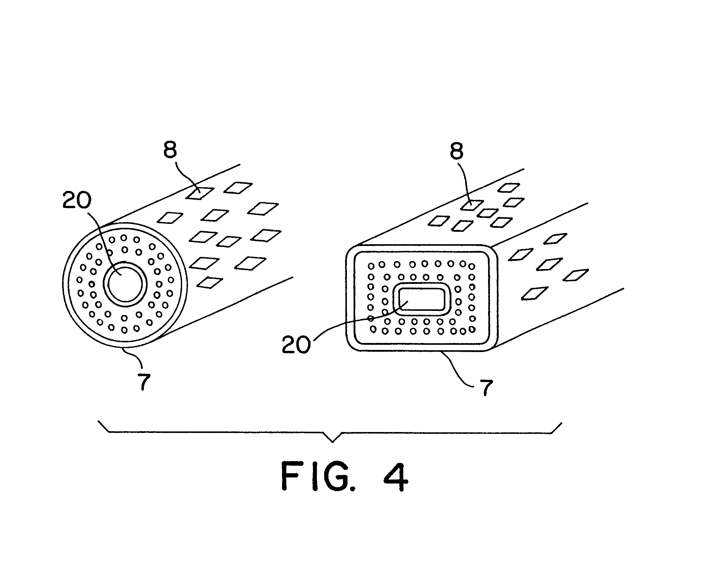
Typical shapes would be a circular FIG. 3a or rectangular cross section FIG. 3b. An advantage for the rectangular shape is that the distance for the acid to penetrate for complete copper removal is reduced. Internal copper stabilization can be introduced as shown in FIG. 4. The Ta clad copper appears as a central core with a Ta diffusion barrier layer and it also reduces the leaching time. Thereafter, the copper-free confined bundle of Nb filaments is infiltrated with liquid Sn or CuSn alloy to thoroughly coat and embed each Nb filament in a solid Sn or CuSn alloy matrix. The Sn is then reacted with Nb to form Nb.sub.3 Sn in a separate step. Temperatures between 700.degree. C. to 1100.degree. C. are used, both performed in an inert atmosphere or vacuum chamber. The Nb-filaments may be reacted partially, completely or it can be completed at a later stage in the manufacture, e.g. after cabling or winding in a magnet.

Problems solved by technology

However, the need for stable, fine filaments and twisted conductors soon made this method obsolete.
Extended time in liquid Sn baths at these temps can result in some Nb loss.
Because of this, the time for the infiltration should be very short.
Intensive efforts directed over the past two decades toward optimizing the Nb:Cu:Sn ratios has all but reached its limits due to the concomitant decrease in its fabricability as the Sn fraction is increased.

Method used


Image

  • Process for making constrained filament niobium-based superconductor composite
  • Process for making constrained filament niobium-based superconductor composite
  • Process for making constrained filament niobium-based superconductor composite

Examples


example ii

In Example I, a continuous sheath, as shown in FIG. 2, was employed and at the final size the conductor was mechanically perforated as shown in FIGS. 3a and 3b to allow for the removal of the copper matrix by acid leaching followed by liquid tin infiltration at high temperatures. It was also shown that the sheath can be applied separately after the conductor has been fabricated by means of taping FIG. 5, Braiding FIG. 6, or by mechanically confining the conductor into a support structure as shown in FIGS. 7, 8 and 9.

A simpler and considerably less expensive method has been found which accomplishes the same objective. The sheath is constructed exactly as in Example I except now a narrow opening is left which is parallel to and runs the length of the filaments shown in FIG. 10.

The size of the opening can be adjusted to permit rapid copper removal of the matrix by acid leaching and still retain the sheath's ability to constrain and support the filaments. Following the final reduction, ...


PUM

PropertyMeasurementUnit
thicknessaaaaaaaaaa
magnetic fieldsaaaaaaaaaa
temperaturesaaaaaaaaaa

Abstract

A niobium-based superconductor is manufactured by establishing multiple niobium components in a billet of a ductile metal, working the composite billet through a series of reduction steps to form the niobium components into elongated elements, each niobium element having a thickness on the order of 1 to 25 microns, surrounding the billet prior to the last reduction step with a porous confining layer of an acid resistant metal, immersing the confined billet in an acid to remove the ductile metal from between the niobium elements while the niobium elements remain confined by said porous layer, exposing the confined mass of niobium elements to a material capable of reacting with Nb to form a superconductor.

Description

The present invention pertains to the fabrication of A-15 type multifilament composite superconductors (By "A-15" is meant the inter metallic compounds having .beta.W structure). These include Nb.sub.3 Sn, and Nb.sub.3 Al and are important because of their superior high field properties. Unfortunately, they are brittle compounds, difficult to make as fine filaments and as a result are very expensive. For these reasons, the ductile NbTi superconductors has dominated the commercial market even though its maximum magnetic field are limited to less than 8 Tesla. Significant improvements are needed in order to commercialize the A-15 conductors and to extend the useful magnetic fields to the 12 Tesla range on a cost effective basis. The present invention is also applicable to the production of the "B1" superconductors NbN and NbC.Standard Industrial PracticeA detailed description of present day methods currently being used in the industry is described in an article entitled "A-15 Supercon...

Claims


Application Information

Patent Timeline
Patent Type & Authority Patents(United States)
IPC IPC(8): C23C2/04C23C2/28C23C2/08C23C2/02G06Q10/00H01L39/24G06Q10/02H01B13/00
CPCC23C2/02C23C2/08G06Q10/02H01L39/2409C23C2/28Y10T29/49014H10N60/0184C23C2/024C23C2/022
Inventor WONG, JAMES
Owner COMPOSITE MATERIALS TECH
Why Eureka
Try Eureka