High efficiency high voltage low EMI ignition coil

a high-efficiency, low-emi technology, applied in the direction of structural circuit elements, machines/engines, cathode-ray/electron beam tube circuit elements, etc., can solve the problems of high-efficiency coil structures that are susceptible to electrical breakdown, not industry practice to encapsulate the entire coil structure, and very inefficient current cd and inductive ignition systems

Inactive Publication Date: 2003-04-08
WARD MICHAEL A V
View PDF2 Cites 26 Cited by
  • Summary
  • Abstract
  • Description
  • Claims
  • Application Information

AI Technical Summary

Problems solved by technology

Current CD and inductive ignition systems are very inefficient, with secondary winding resistance in the thousands of ohms, and typically using spark plug wire with resistance in the 5,000 to 10,000 ohms per foot, and resistive spark plugs which typically have resistance of about 5000 ohms.
Such high efficiency coil structures are susceptible to electrical breakdown across their last secondary winding bay upon ignition firing at a preferred high breakdown voltage of 30 to 40 kV.
However, it is not industry practice to encapsulate the entire coil structure because of the large differences in expansion coefficient between the magnetic laminations and copper wire and the bobbin and the encapsulant (usually an epoxy).

Method used


Image

  • High efficiency high voltage low EMI ignition coil
  • High efficiency high voltage low EMI ignition coil
  • High efficiency high voltage low EMI ignition coil

Examples


Embodiment Construction

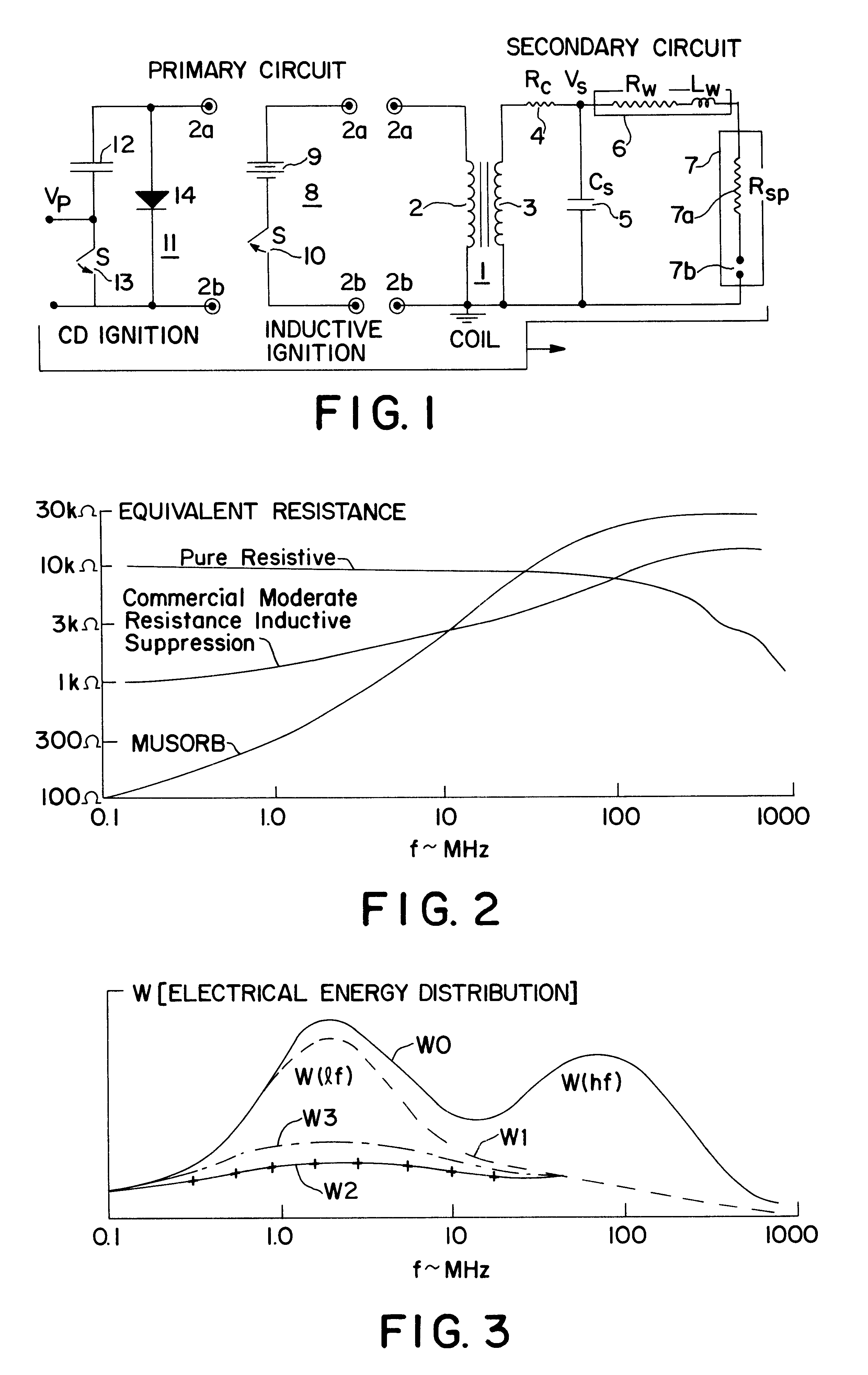
FIG. 1 is a circuit diagram of an ignition system depicting a secondary circuit with a single coil 1 with primary winding 2, secondary winding 3, coil secondary resistance 4 (resistance Rc), coil output capacitor 5 (capacitance Cs), and completing the secondary circuit is spark plug wire 6 (with resistance Rw and inductance Lw), and the spark plug 7 with resistor 7a (resistance Rsp) and spark gap 7b. Connected to the primary terminals 2a and 2b of the coil 1 are shown the two basic forms of primary circuit, an inductive ignition circuit 8 with battery 9 and switch 10 (normally closed switch S), and a CD ignition circuit 11 with capacitor 12 charged to a voltage Vp, switch 13 (normally closed switch S), and shunt diode 14 shown in the preferred mode shunting the primary coil winding 2. The operations of these two circuits is well known to those versed in the art and is disclosed in the cited patents and patent applications.

Typically, the spark plug wire resistance Rw is 5,000 to 10,0...


PUM


Abstract

A high efficiency high voltage ignition coil with segmented high voltage bobbin (15) with the last few bays (16,17,18) having fewer secondary winding turns than the average and thicker flanges separating the bays, and further including an inductor (20) of inductance at least 0.5 mH with a core material which is lossy in the 100 KHz to 1 MHz range, the inductor located between the end of the high voltage winding and the spark gap (7b) so as to reduce the peak voltages across the last few high voltage bays immediately following the spark gap breakdown.

Description

This invention relates to ignition coils for internal combustion (IC) engines, both capacitive discharge (CD) and inductive. In particular, it relates to modern ignition coils with segmented bobbins in which the secondary winding is wound in separate bays, and more particularly to high efficiency ignition coils, both CD and inductive, which have a low secondary resistance typically in the 100 to 500 ohm range and use spark plug wires and spark plugs with direct current (DC) resistance substantially less than 1000 ohms. The invention addresses issues of transient high voltage resulting from ignition spark firing of such high efficiency coils, in particular issues associated with the high voltage spark discharge as it reflects itself in the ignition coil high voltage "end-effects" and electromagnetic interference (EMI). In addition, this invention relates to systems for fabricating and encapsulating such high efficiency coils with the improvements made to resolve the end-effect and EM...

Claims


Application Information

Patent Timeline
Patent Type & Authority Patents(United States)
IPC IPC(8): F02P3/02F02P3/04
CPCF02P3/02F02P3/0435
Inventor WARD, MICHAEL A. V.
Owner WARD MICHAEL A V
Why Eureka
Try Eureka