Method of producing silicon carbide

a technology of silicon carbide and silicon vapor, which is applied in the direction of single crystal growth details, chemically reactive gases, and condensed vapors. it can solve the problems of difficult to obtain the required grain size powder, serious limitations on the industrial potential of this remarkable material, and high cost and time consumption. achieve the effect of preventing or minimizing the condensation of silicon vapor

Inactive Publication Date: 2003-04-29
SILBID
View PDF11 Cites 15 Cited by
  • Summary
  • Abstract
  • Description
  • Claims
  • Application Information

AI Technical Summary

Benefits of technology

According to a broad aspect of the present invention, there is provided a method of producing silicon carbide (SiC), comprising: introducing into the interior of a furnace a graphite crucible containing a quantity of elemental silicon, and a quantity of elemental carbon free of water, at least the elemental silicon being in the form of finely-divided particles, the quantity of silicon being in excess of the quantity of carbon by weight; subjecting the interior of the furnace to a vacuum; and heating the silicon and carbon to a temperature of 1500.degree. C.-2200.degree. C. to vaporize the silicon and to convert the carbon to silicon carbide, the crucible being at least partly open at its upper end to the interior of the furnace to permit excess silicon vapors to escape and thereby avoid deposition of silicon on the outer surface of the silicon carbide.
According to another aspect of the present invention, there is provided a method of producing a shaped article of silicon carbide (SiC), comprising: preparing a mixture of a quantity of carbon in the form of finely-divided particles mixed in a binder; shaping said mixture according to the desired shape of the article; applying finely-divided particles of silicon over the outer surface of said shaped article; introducing the shaped article with the finely-divided particles of silicon thereover into a graphite crucible, and introducing the crucible into the interior of a furnace; subjecting the interior of the furnace to a vacuum; and heating the interior of the furnace to a sufficiently high temperature and for a sufficiently long period of time until a resulting product is produced having a green-tinged or yellow-tinged color, the crucible being at least partly open at its upper end to the interior of the furnace to permit excess silicon vapors to escape and thereby avoid deposition of silicon on the outer surface of the silicon carbide.
In the preferred embodiments of the invention described below, the quantity of silicon is in excess of the quantity of carbon by weight to assure relatively complete conversion of the carbon to silicon carbide, with the excess silicon being removed by removing the silicon vapors during the diffusion process to prevent or minimize condensation of the silicon vapor on the outer surface of the silicon carbide.

Problems solved by technology

Moreover, it is difficult to obtain a powder of the required grain size with this process.
However, these techniques are also relatively expensive and time-consuming, such that they impose serious limitations on the industrial potential of this remarkable material.
In addition, silicon carbide heating or lighting elements prepared in accordance with these known techniques generally vary in resistance with temperature, and / or lose power with age, thereby requiring extra controls, special compensations, and / or frequent replacement.

Method used


Image

  • Method of producing silicon carbide
  • Method of producing silicon carbide
  • Method of producing silicon carbide

Examples


example 1

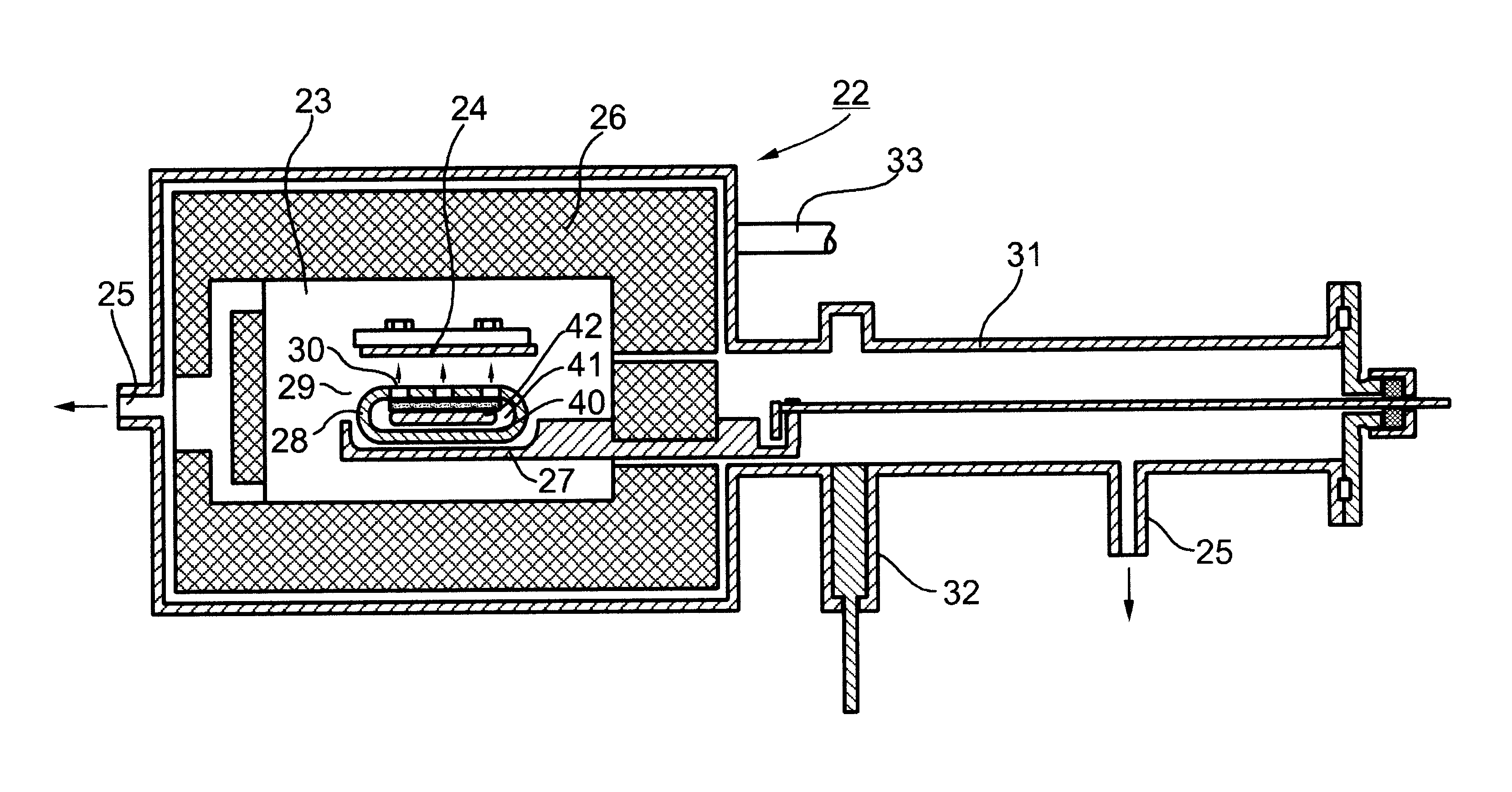
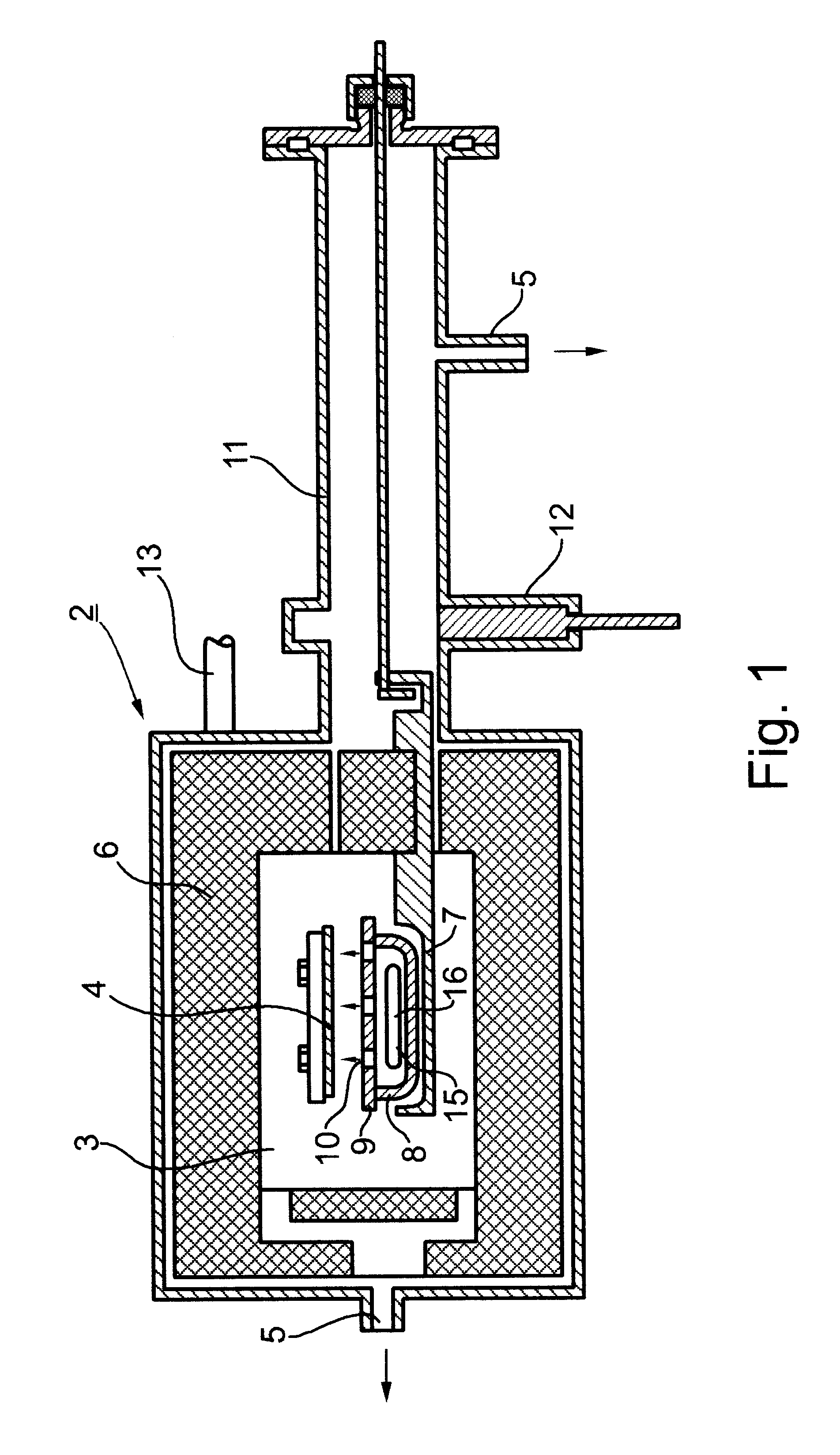
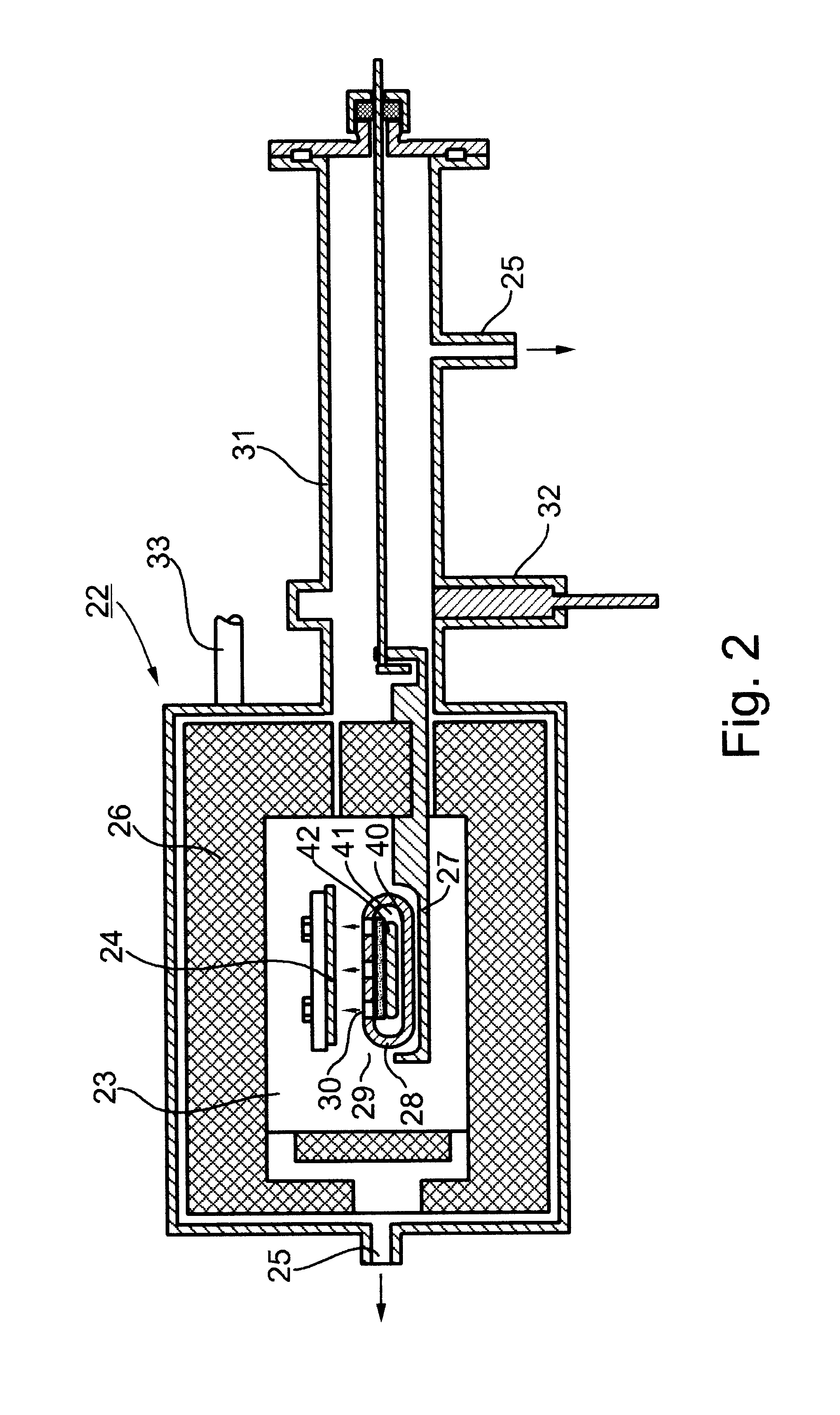
In this example, the carbon particles used for making the shaped workpiece 15 are finely-divided particles of charcoal having a particle size of 50-250 microns; and the silicon particles 16 applied over the shaped workpiece 15 are finely-divided particles of the waste of silicon wafers, both the mono-crystalline and the poly-crystalline type, resulting from the production of semiconductor devices, also ground to a fine particle size.

The initial composition preferably includes 54% silicon and 46% carbon by weight, with the silicon being relatively pure but including traces of dopants, such as zinc, aluminum, and / or tellurium, in the ratio of about 1:10.sup.-6. Such dopants reduce the internal resistance of the produced silicon carbide composition.

The carbon particles are mixed in a binder of white sugar (sucrose) dissolved in soft water (one kilogram of white sugar with a few liters of water), which water was subsequently evaporated. The carbon particles are homogeneously mixed in th...

example 2

This example was the same as in Example 1, except that the finely-divided particles of carbon are mixed in a binder of polyvinyl acetate, in an amount of 0.5 kg polyvinyl acetate to one kg. of carbon, instead of the sugar solution. The process is otherwise the same as in Example 1.

example 3

This example is also the same as in Example 1, except that the sample is heated to a higher temperature of 1800.degree. C. for a shorter period of time, 30 minutes. The rest of the procedure is substantially the same as in Example 1.


PUM

PropertyMeasurementUnit
temperatureaaaaaaaaaa
temperaturesaaaaaaaaaa

Abstract

A method of producing silicon carbide (SiC), by introducing into the interior of a furnace a quantity of relatively pure elemental silicon and a quantity of elemental carbon; subjecting the interior of the furnace to a vacuum; and heating the silicon and carbon to a temperature of 1500° C.-2200° C. to vaporize the silicon and to react it with the carbon to produce silicon carbide. Several embodiments are described for producing a heating or lighting element and a high temperature sensor, respectively, in which the carbon is in the form of a shaped body made of a mixture of finely-divided particles of carbon in a binder, and the silicon is in the form of finely-divided particles applied to the outer surface of the shaped body. A further embodiment is described for producing silicon carbide powder, in which the carbon and silicon are each in the form of finely-divided particles, and are physically separated from each other by a graphite sheet permeable to silicon vapor.

Description

FIELD AND BACKGROUND OF THE INVENTIONThe present invention relates to a method of producing silicon carbide (SiC). The method is particularly useful for producing silicon carbide heating and lighting elements, high-temperature sensor elements, and finely-divided particles of silicon carbide, (e.g., for use as abrasives, for hardening surfaces, etc.), and the invention is therefore particularly described below with respect to these applications. However, it will be appreciated from the description below that the novel method could also be used for producing silicon carbide for many other applications, such as semi-conductor substrates, hard coatings for turbine blades, high power switching devices, cosmic radiation protectors, etc.Silicon carbide (SiC), sometimes referred to as carborundum, is a hard, clear, green-tinged or yellow-tinged crystalline compound, which is normally insulating but which becomes conductive when properly heated at a high temperature; for example, when heated...

Claims


Application Information

Patent Timeline
Patent Type & Authority Patents(United States)
IPC IPC(8): C30B23/00C30B23/02
CPCC30B23/00C30B23/02C30B29/36
Inventor GOLAN, GADY
Owner SILBID
Why Eureka
Try Eureka