High resolution biosensor system

a biosensor and high-resolution technology, applied in the field of biosensors, can solve the problems of limited sensitivity of first-generation biosensors, inability to detect low concentration test targets in a short period of time, and inability to precisely measure the variation of biological phenomena in real tim

Inactive Publication Date: 2003-05-06
ANT TECH CO LTD
View PDF8 Cites 16 Cited by
  • Summary
  • Abstract
  • Description
  • Claims
  • Application Information

AI Technical Summary

Benefits of technology

As the density and viscosity of the solution remain constant, the frequency variation (.DELTA.F) is directly proportional to the variation of the mass load (.DELTA.M). However, the precision of the frequency counter used in traditional biosensor systems can only reach 1 Hz. If the base clock is 10 MHz, the ultimately detectable limit can only be 0.43.times.10.sup.-9 g (approximately corresponding to 4.3.times.10.sup.-6 g / ml). The present invention utilizes a phase-lock loop (PLL) circuit to generate a counting signal that has the same phase as the base clock, but the frequency thereof is n times higher than that of the base clock, such that the resolution can be raised n times. For instance, if n=100, the frequency for the resolution can reach 0.01 Hz and the ultimately detectable limit can be up to 4.3.times.10.sup.-12 g (approximately corresponding to 4.3.times.10.sup.-9 g / ml). This invention may vastly enhance the precision of measurement and improve the identification sensitivity of biological target by up to 100 times, and thus reach the virus level of identification. Furthermore, the PLL circuit comprises a filter for tracing phase error, and utilizes a closed loop servo control to maintain the phase relation. Therefore, the frequency jittering problem customarily caused by noises in input signals can be overcome, because the output signal of PLL does not disappear with the instantaneous variation, such that the S / N ratio can be raised and a stable output frequency can be achieved.

Problems solved by technology

In the fast developing field of biology and medical technology, it is an obstacle to the advancement that people cannot precisely measure the variation of biological phenomenon in real time to realize the function of the variation.
However, the sensitivity of such first generation biosensors is limited by the weak conjugation between the biomolecule-enzyme and the test target.
Even though the enzyme possesses the ability to amplify the signal, there still exists a defect in which a test target of low concentration cannot be detected in a short period of time.
Although these products may achieve high resolution, they are not economical and practical because of their difficult technologies and their high price, for example, US $300,000 dollars.
In addition, the price of their consumable detection chips, which cost $200 US dollars for each chip, is also very expensive.
As a result, it is quite difficult to popularize these products.
However, the precision of the frequency counter used in traditional biosensor systems can only reach 1 Hz.

Method used


Image

  • High resolution biosensor system
  • High resolution biosensor system
  • High resolution biosensor system

Examples


example 1

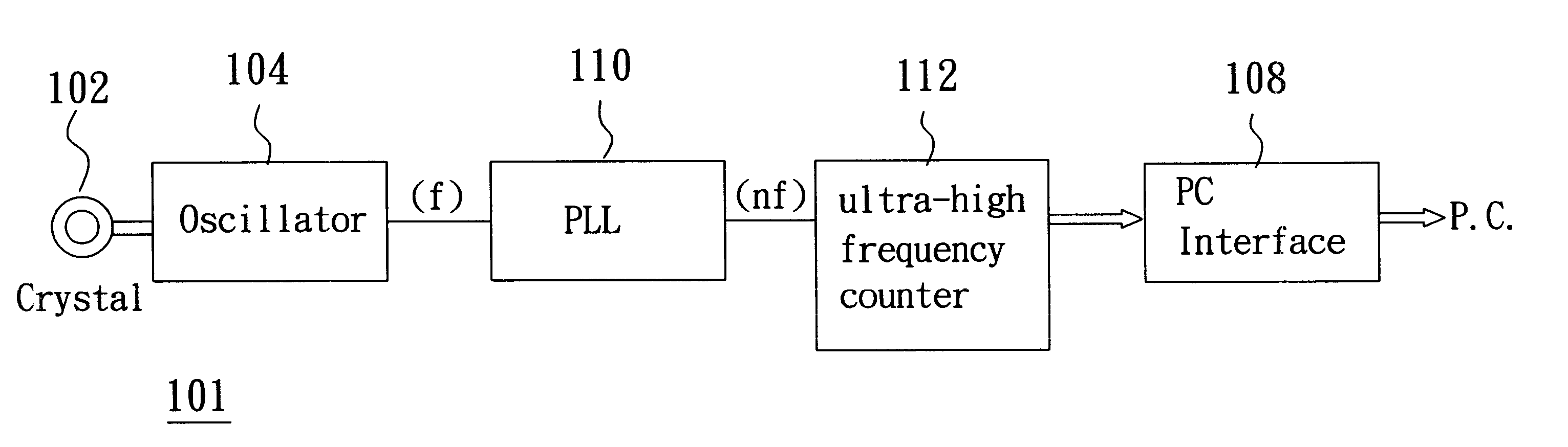
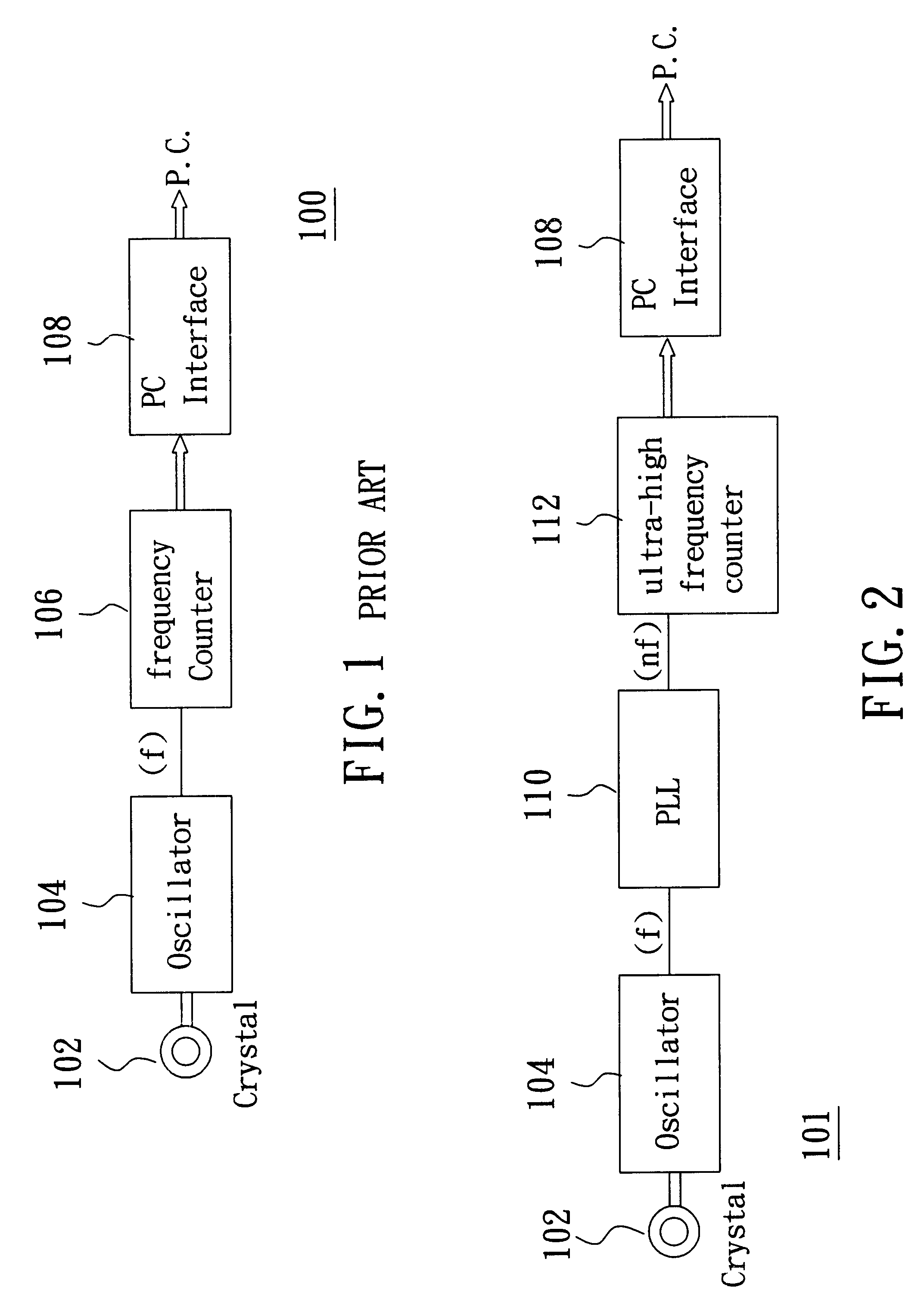
As illustrated in FIG. 7, if we incorporate and calculate the time of the last one pulse, .phi., then we can raise the resolution of the bio-sensor. This invention employs the PLL circuit to achieve said purpose. The PLL circuit (110) is used to produce a signal with the same phase as the original signal, but the frequency thereof has been raised n times in a cycle. As shown in FIG. 7, if the original frequency f equals "a+.phi.", and "a" is an integer, since .phi.<1, the detectable frequency f is "a". Now we raise the frequency by n times, nf, nf=na+b+.phi.', wherein b=.phi.-.phi.'and is an integer. So, if "na+b" can be detected but .phi.', which is less than 1, cannot be detected, (nf) will be "na+b". If nF is divided by n, then we can get the original frequency f, (na +b) / n=a+(b / n). Therefore, we get the frequency count number of "a+(b / n)". In other words, the resolution has been raised n times.

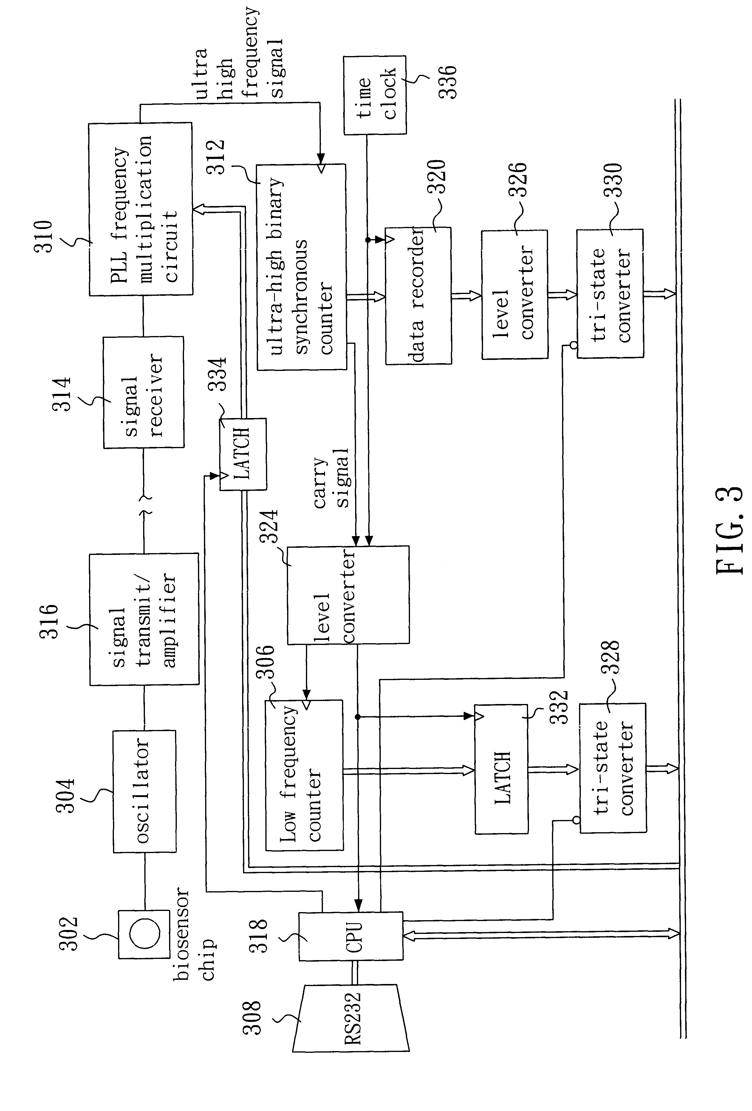
On the other hand, since the PLL circuit (110) comprises a filter (404) to trace the ...


PUM

PropertyMeasurementUnit
concentrationaaaaaaaaaa
frequencyaaaaaaaaaa
frequencyaaaaaaaaaa

Abstract

A high resolution biosensing system for detecting and identifying a biochemical material to be tested by using proportional relationship between frequency variation of oscillation and mass of the biochemical material to be tested comprises a biosensor; an oscillatorfor generating oscillation based on the sensed result; a phase-lock loop circuit receiving the oscillation of the oscillator and generating pulse signals;an ultra-high frequency counter for counting the pulse signals; and a microprocessor for storing and displaying output from the ultra-high frequency counter and for controlling the oscillator. The phase-lock loop circuit generates the pulse signals of a frequency, which is n times the frequency of the oscillator and with a constant phase difference therebetween to trigger the ultra-high frequency counter. Accordingly, the resolution can be raised up to n times.

Description

BACKGROUND OF TECHNOLOGYIn the fast developing field of biology and medical technology, it is an obstacle to the advancement that people cannot precisely measure the variation of biological phenomenon in real time to realize the function of the variation. Since 1990, a biosensor system has been defined as an apparatus which utilizes immobilized biomolecules in combination with a transducer to detect in vivo or in vitro chemicals or produce a response after a specific interaction with the chemicals. The biomolecules comprise molecule identifying elements for the tissue of an organism or an individual cell. Such elements are used for receiving or generating biosensor signals. The transducer is a hardware instrument element that mainly functions as a physical signal converting element. Consequently, a biosensor system can be constituted by combining specific biologically active materials, which can be obtained by isolating, purifying or inventively synthesizing the materials via bioche...

Claims


Application Information

Patent Timeline
Patent Type & Authority Patents(United States)
IPC IPC(8): G01N29/02G01N29/036G01N29/36G01N29/34
CPCG01N29/036G01N29/348G01N29/36G01N2291/101G01N2291/02466
Inventor CHANG, I-NANLO, CHUNG CHIHCHEN, WU CHINCHEN, YEN-WEN
Owner ANT TECH CO LTD
Why Eureka
Try Eureka