Refuelable and rechargeable metal-air fuel cell battery power supply unit for integration into an appliance

Inactive Publication Date: 2003-05-27
REVEO
View PDF79 Cites 53 Cited by
  • Summary
  • Abstract
  • Description
  • Claims
  • Application Information

AI Technical Summary

Benefits of technology

Accordingly, a prime object of the present invention is to substitute the traditional power supply unit and methodology (typically, one or more switching power regulators) integrated in an electrical system or device with a power supply unit comprising one or more rechargeable and refuelable metal-air FCB-based subsystems. This solution is, energy efficient, environmentally-friendly, and reliable, thus enabling consumers to use the system/device without the risk and limitations of prolonged interruption. Moreover, the solution is cost-effect because it eliminates the need

Problems solved by technology

However, the reliability of this power grid is fragile and can be compromised by unpredictable severe weather (snow/ice storms, earthquakes, tornadoes, hurricanes), system failure (excessive demand, lack of supply of natural gas to generation systems) and/or human error.
Ice accumulation on trees and overhead lines caused hundreds of millions of dollars of damage in both the United States and Canada and left hundreds of thousands of people without power for periods ranging from a few hours to more than three weeks.
In another example, during the unusually hot summer of 1988, the power infrastructure of Auckland, New Zealand unpredictably could not handle the stress caused by the extreme demand, and the aging underground transmission cables that were vital to feeding the city with electricity failed in succession.
Thus, previous failures of the power grid have shown that the disruptions caused by such failures can be massive, especially if the failures are prolonged.
However, the reliability of many of these alternate power generation systems is also fragile.
For example, the supply of power from solar-powered generation systems/wind-powered generation systems/hydroelec

Method used


Image

  • Refuelable and rechargeable metal-air fuel cell battery power supply unit for integration into an appliance
  • Refuelable and rechargeable metal-air fuel cell battery power supply unit for integration into an appliance
  • Refuelable and rechargeable metal-air fuel cell battery power supply unit for integration into an appliance

Examples


Embodiment Construction

Of the Present Invention should be read in conjunction with the accompanying Drawings, wherein:

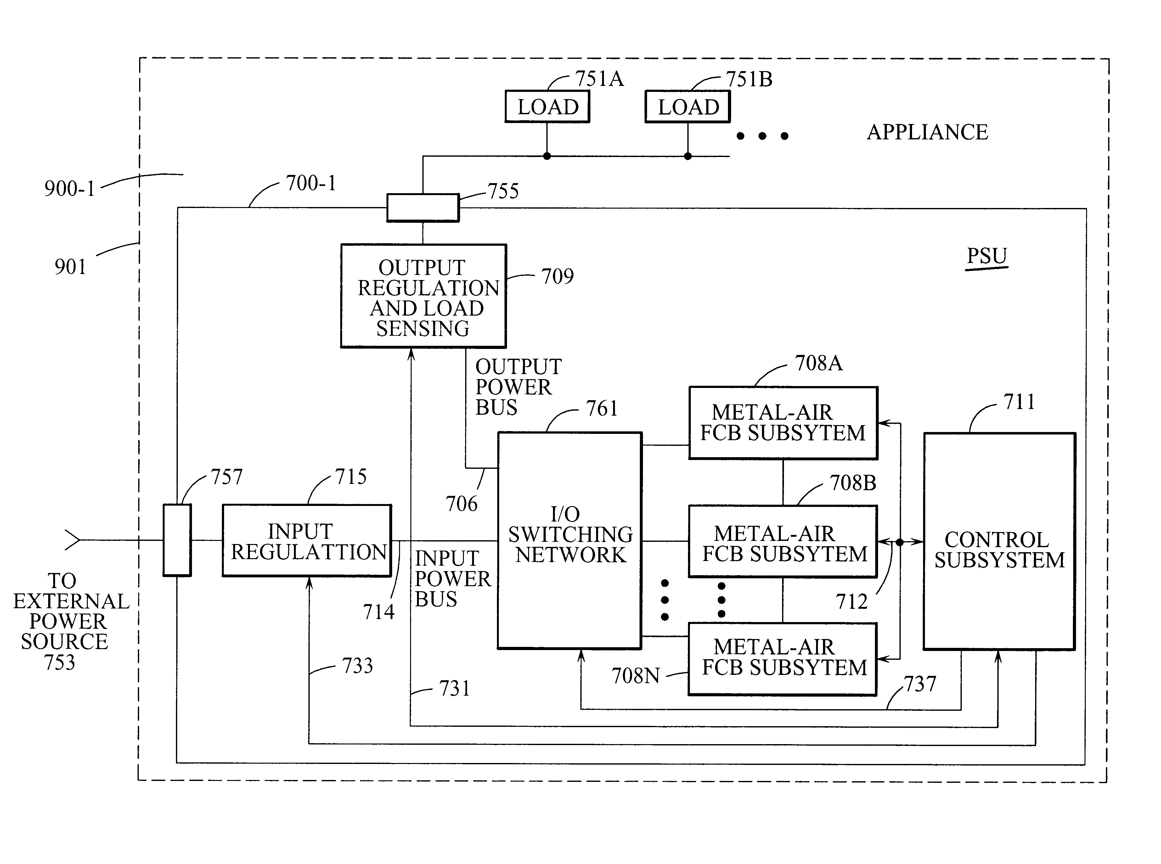
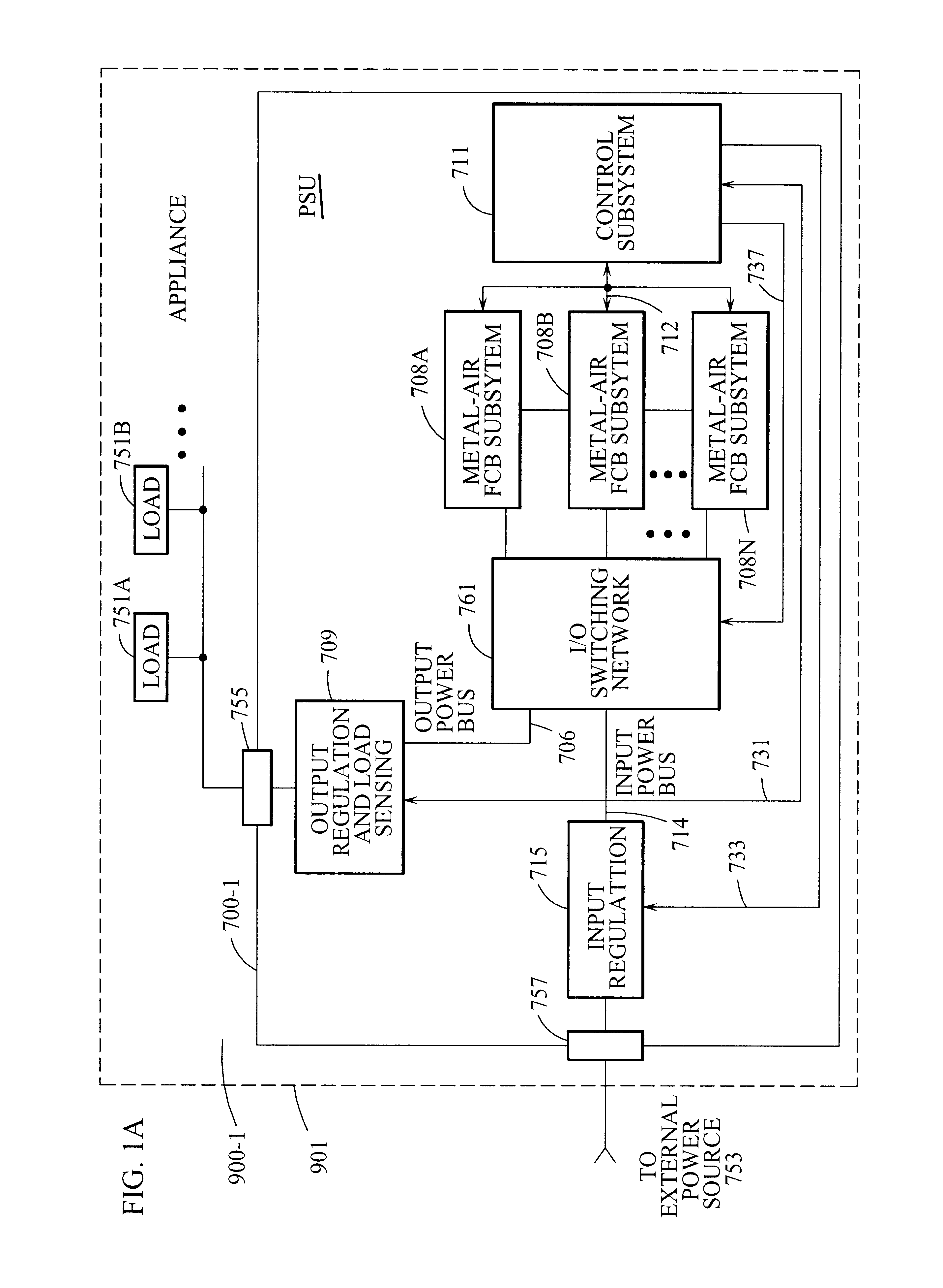
FIG. 1A is a schematic representation of a generalized embodiment of a device / system have an integrated power supply unit utilizing refuelable and rechargeable metal-air FCB technology, wherein a network of metal-air FCB subsystems are operably connected to a power bus structure and controlled by a control subsystem.

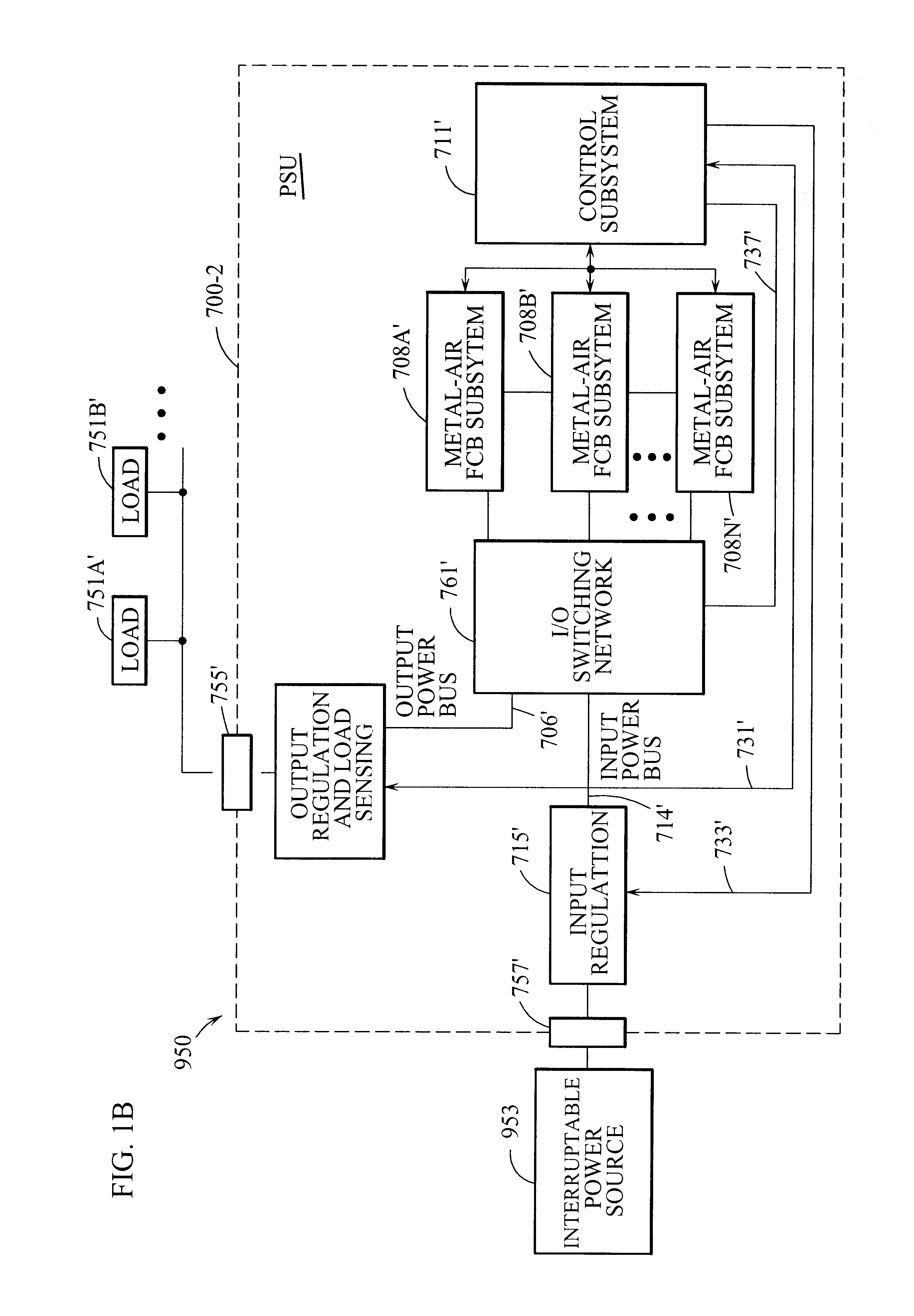
FIG. 1B is a schematic representation of a generalized embodiment of a power generation and distribution system using a refuelable and rechargeable metal-air FCB based power supply unit, wherein a network of metal-air FCB subsystems are operably connected to a power bus structure and controlled by a control subsystem.

FIG. 1C is a schematic representation of a generalized embodiment of the refuelable and rechargable metal-air FCB based power supply unit of the present invention, wherein a network of metal-air FCB subsystems are operably connected to a power bus structure and con...


PUM


Abstract

A refuelable and rechargable metal-air FCB based power supply unit for integration into a device/system for generating and providing electrical power to at least one electrical-energy-consuming load device disposed therein. An external power source is used to recharge the metal-air FCB subsystems embodied therein. A control subsystem automatically transitions between discharging mode (wherein at least one metal-air FCB subsystem supplies electrical power to the electrical power-consuming load device) and a recharging mode (wherein the external power source is electrically coupled to at least one metal-air FCB subsystem to thereby recharge the metal-air FCB subsystem(s). The metal-air FCB subsystem(s) are refueled by manually loading and unloading metal-fuel from the metal-air FCB subsystem(s). Preferably, electrical power provided to the at least one electrical power-consuming load device is supplied solely by electrical power generated by discharging metal-fuel in the metal-air fuel cell battery subsystem(s). In addition, the metal-air FCB subsystem(s) preferably has a modular architecture that enable flexible and user-friendly operations in loading of metal-fuel, unloading of consumed metal-fuel, replacement of the ionic-conducting medium, and replacement of the cathode.

Description

1. Field of the InventionThe present invention relates to improved methods and systems for electrochemically producing electrical power using metal-air fuel cell battery (FCB) technology.2. Description of the Related ArtAn ever-expanding range of electrical systems and devices are vital to the normal continuation of daily life for individuals and businesses in today's society. Such systems and devices include portable devices (radio / tape / CD / DVD systems, PDA devices, notebook computers, cell phones, video equipment, calculators, fans, lawn mowers, screw drivers, drills, saws), appliances (refrigerators, freezers, air conditioners, toasters, televisions, audio equipment, washing machines, ovens, stoves, and furnaces), transportation devices (power passenger vehicles, buses, golf carts, motorcycles, boats, etc), computer processing and telecommunication equipment (servers, desktop computers, communication routing and switching systems) and the electrical infrastructure in homes, school...

Claims


Application Information

Patent Timeline
IPC IPC(8): H01M12/06H01M12/00H01M8/04H01M6/50H01M10/42H01M10/44H01M12/08
CPCH01M8/04119H01M8/04291H01M10/44H01M12/08H01M10/425H01M6/5016H01M8/2475Y02E60/50H01M12/06Y02E60/10
Inventor FARIS, SADEG M.TSAI, TSEPIN
Owner REVEO
Why Eureka
Try Eureka