High speed magnetic coil for magneto-optical head

Inactive Publication Date: 2003-06-24
CANON KK
View PDF28 Cites 34 Cited by
  • Summary
  • Abstract
  • Description
  • Claims
  • Application Information

AI Technical Summary

Benefits of technology

It is preferable that the conductor pattern formed at the peripheral edge of the coil have a band shape, and its width be equal to or more than the pitch P of the coil pattern and equal to or less than 4P. A narrower conductor pattern does not substantially reinforce the peripheral edge; or a wider conductor pattern increases the diffusion rate of metal ions in a plating solution and increases the thickness to be much larger than the coil pattern in forming a conductor pattern by plating. If this band-like conductor pattern is formed to be coupled to another conductor pattern in the ineffective region, the coil is reinforced and made more flat. The conductor pattern need not always be formed even at the peripheral edge of the coil as far as the interval between this peripheral edge and the outer edge of the coil pattern is equal to or less than the pitch P of the coil pattern. In this manner, the conductor pattern along the peripheral edge of the coil need not always be completely continuous to form a closed loop, but may be partially disconnected.
A positioning portion such as a circular or oval hole or a recess formed in the outer periphery of the coil is formed in the ineffective region, and a conductor pattern is formed at the peripheral edge of the positioning portion. This increases the mechanical strength around the positioning portion. In the following description, this conductor pattern formed at the peripheral edge of the positioning portion will be called a "guide pattern". Forming the guide pattern prevents the coil from deforming in fitting the positioning portion of the coil on a locking member attached to another building member such as the slider of the magnetic head. The relative positional precision to the optical head can further increase.
The conductor pattern formed in the ineffective region dissipates heat generated by the coil pattern or core formed in the effective region, thereby preventing the temperature rise of the magnetic head. A magnetic head having a heat dissipation member in tight contact with the conductor pattern can obtain high heat dissipation efficiency.
In the ineffective region, a conductor pattern having an appropriate shape can be formed at an appropriate position in accordance with the purpose. If all conductor patterns are formed such that their conductor occupation ratios R satisfy inequalities 1, 2, and 3, the mechanical strength of the coil increases without degrading the electrical characteristics of the coil. All conductor patterns including the coil pattern have almost the same thickness, which prevents some of the conductor patterns from protruding from the

Problems solved by technology

However, the above-described flat coil is low in rigidity and mechanical strength, readily deforms in manufacturing a magnetic head, and is difficult to be adjusted to an accurate position.
Thus, the above demands cannot be met.
Since the thin resin material sheet is very flexible, the coil 50 is insufficient in rigidity, posing the following problem in manufacturing a magnetic head.
As a result, the attaching position of the coil 50 is not accurately d

Method used


Image

  • High speed magnetic coil for magneto-optical head
  • High speed magnetic coil for magneto-optical head
  • High speed magnetic coil for magneto-optical head

Examples


example 1

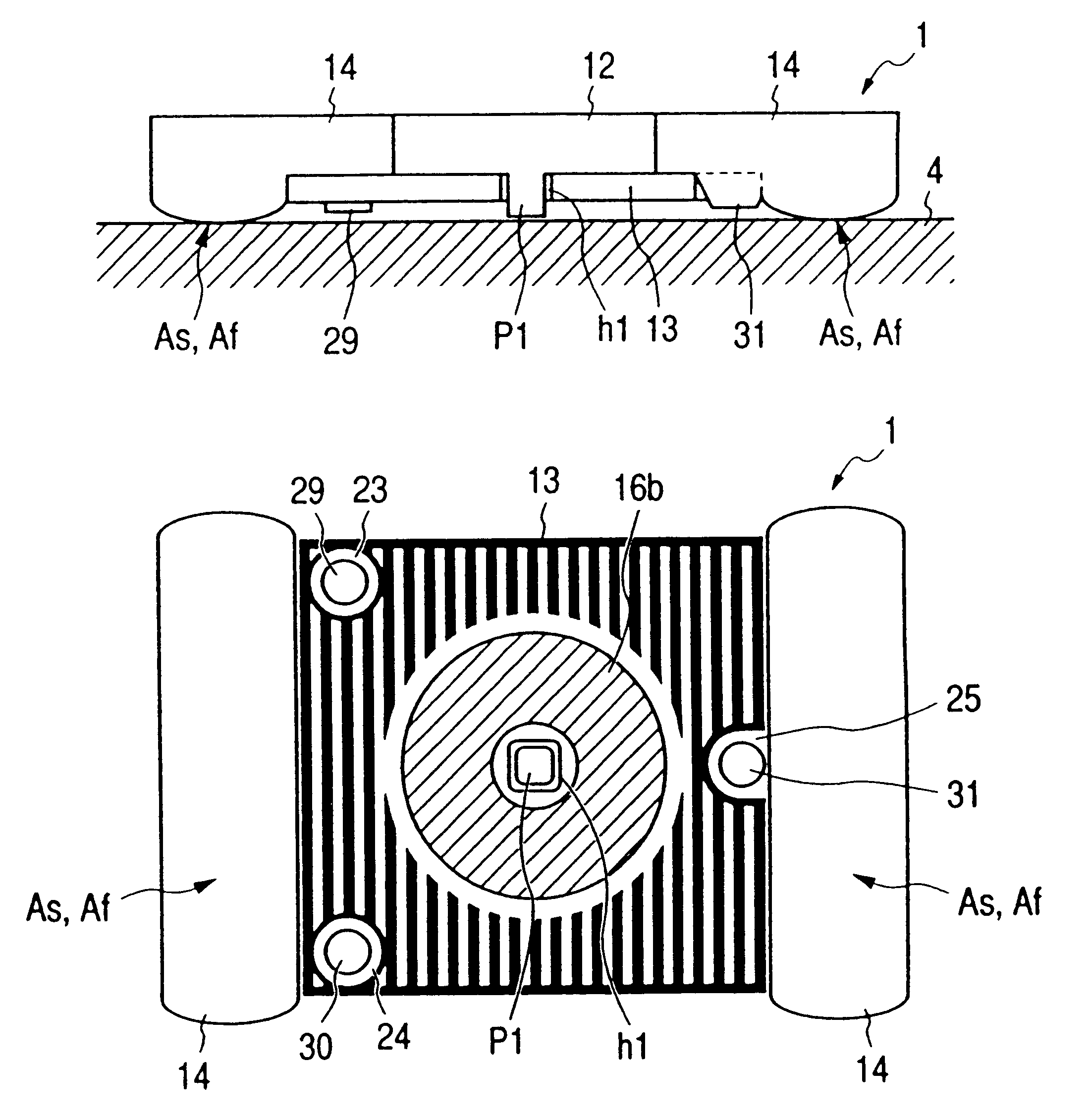
FIGS. 11A and 11B show the structure of a magnetic head 1. FIG. 11A is a side sectional view, and FIG. 11B is a bottom view. The magnetic head 1 is constituted by a core 12 made of a magnetic material such as ferrite, a coil 13, and a slider 14 which mounts them. Reference numeral 4 denotes a magneto-optical disk serving as a magneto-optical recording medium.

The core 12 is made of a magnetic material such as ferrite with a flat shape, and its center has a projecting magnetic pole p1 with a prism shape. The coil 13 is flat, and its center has a square hole h1. The magnetic pole p1 of the core 12 is inserted in the hole h1. The coil 13 is mounted on the slider 14 together with the core 12. The slider 14 is made of a resin material, ceramic material, or the like, and has a sliding surface As or floating surface Af for sliding on or floating / gliding above the magneto-optical disk 4, so as to face the magneto-optical disk 4.

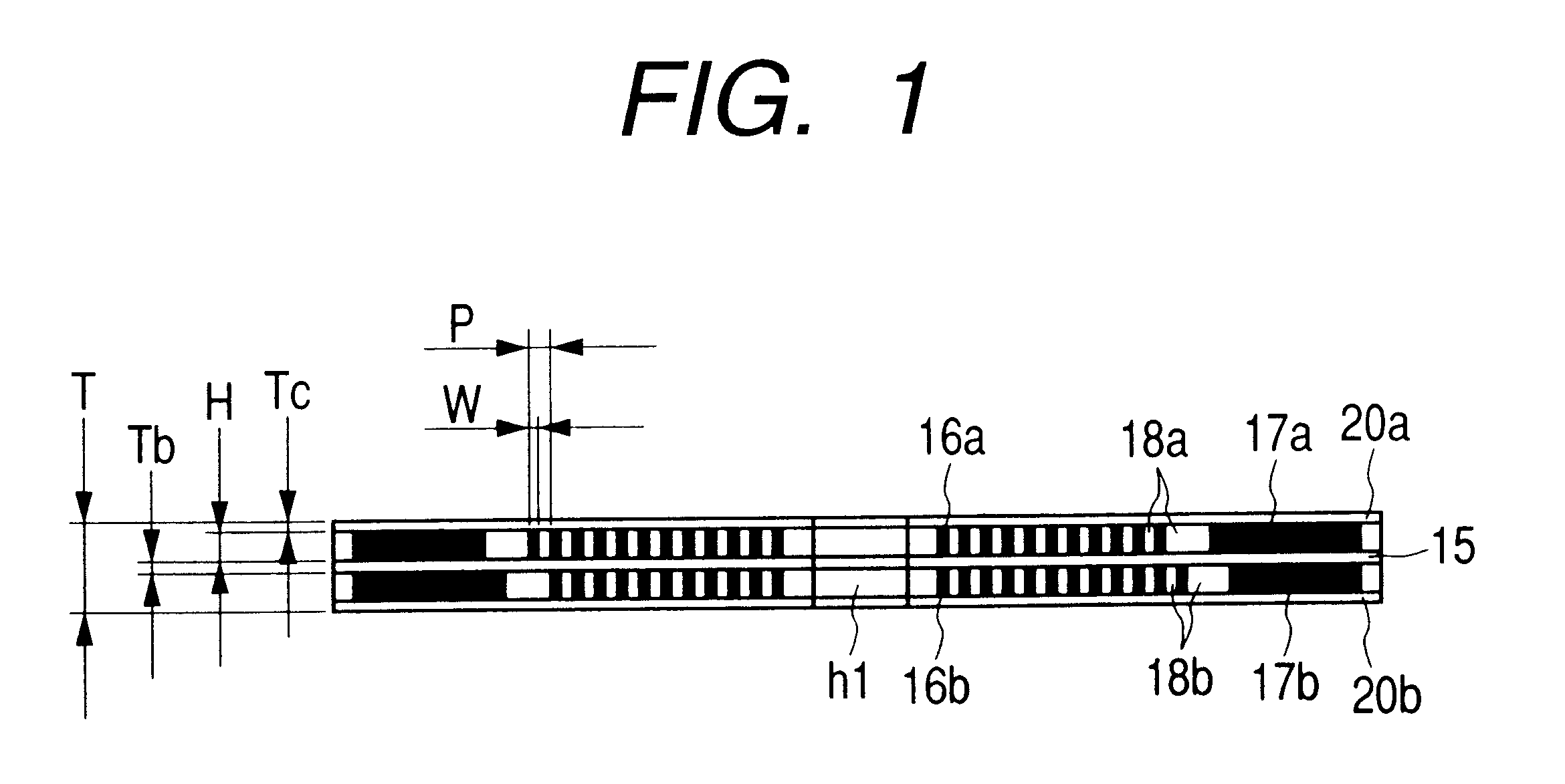
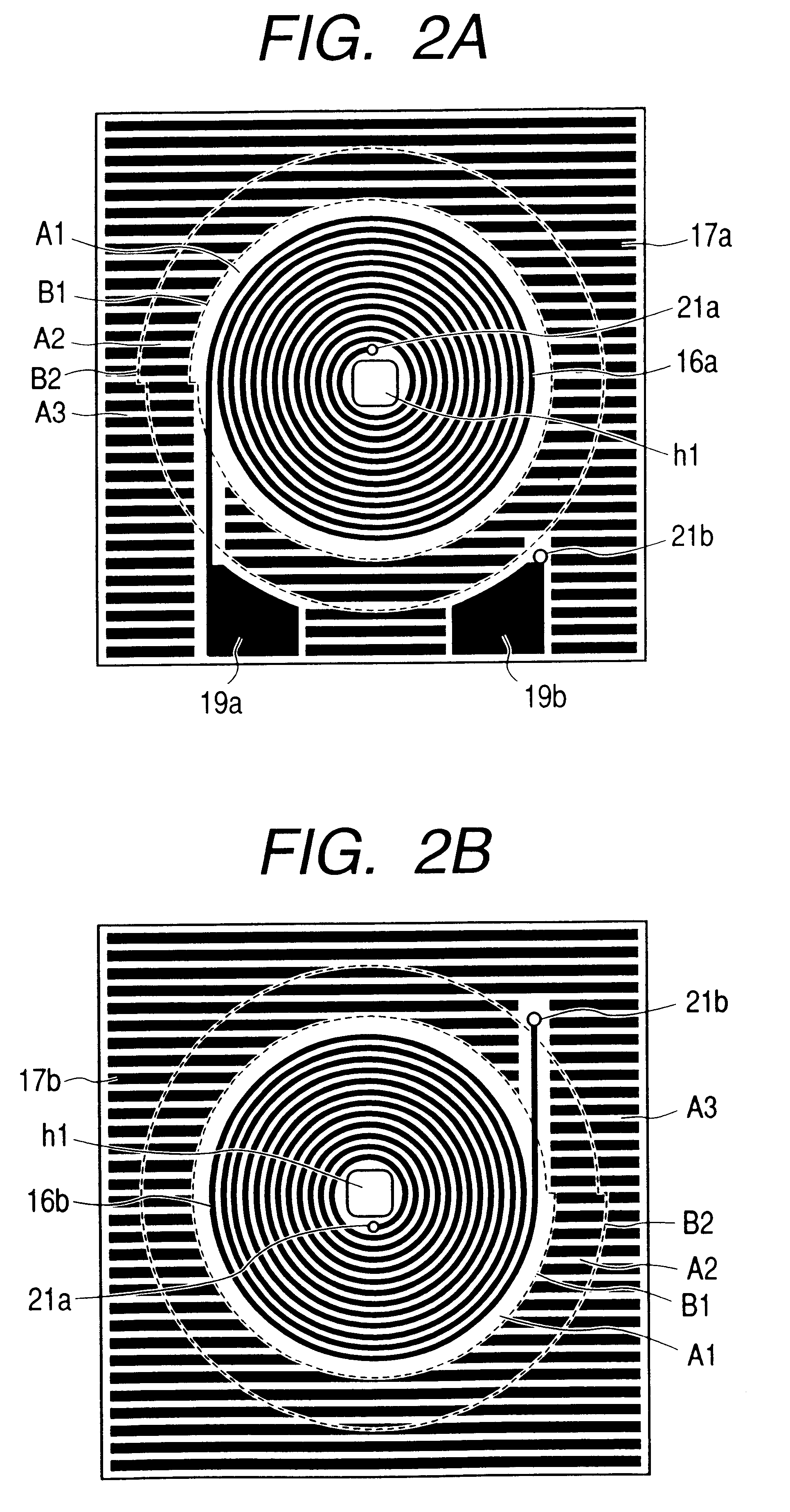
FIGS. 1, 2A, and 2B show the detailed structure of the coil 13. ...

example 2

Example 2 of the present invention will be described. A magnetic head in Example 2 has the same structure as that in Example 1 shown in FIG. 11, and a description thereof will be omitted. FIGS. 3A and 3B show the detailed structure of a coil 13 in Example 2. FIG. 3A is a plan view when viewed from the top, and FIG. 3B is a plan view when viewed from the bottom.

The structure except for conductor patterns formed in the ineffective region is the same as that in Example 1 shown in FIGS. 1 and 2, and a description thereof will be omitted.

The conductor patterns, i.e., dummy patterns 17a and 17b formed in the ineffective region in Example 2 will be described.

Also in Example 2, a region where the distance S from the outer edge of each of coil patterns 16a and 16b satisfies 0 .mu.m.ltoreq.S.ltoreq.60 .mu.m is defined as a first region A1 on both the upper and lower surface sides of the coil 13 in accordance with inequalities 1, 2, and 3; a region where the distance S satisfies 60 .mu.m

example 3

Example 3 of the present invention will be described. A magnetic head in Example 3 has the same structure as that in Example 1 shown in FIGS. 11A and 11B, and a description thereof will be omitted. FIGS. 4A and 4B show the detailed structure of a coil 13 in Example 3. FIG. 4A is a plan view when viewed from the top, and FIG. 4B is a plan view when viewed from the bottom.

The structure except for conductor patterns formed in the ineffective region is the same as that in Example 1 shown in FIGS. 1, 2A, and 2B, and a description thereof will be omitted.

The conductor patterns, i.e., dummy patterns 17a and 17b formed in the ineffective region in Example 3 will be described.

Also in Example 3, a region where the distance S from the outer edge of each of coil patterns 16a and 16b satisfies 0 .mu.m.ltoreq.S.ltoreq.60 .mu.m is defined as a first region A1 on both the upper and lower surface sides of the coil 13 in accordance with inequalities 1, 2, and 3; a region where the distance S satisfie...


PUM


Abstract

The conductor pattern of a magnetic head coil includes a spiral coil pattern to which a current can be supplied to flow around the magnetic field generation center, and a conductor pattern which is formed outside the coil pattern and cannot receive a current so as to flow around the magnetic field generation center. Letting S be the distance from the outer edge of the outermost periphery of the coil pattern, and P be the pitch, a conductor occupation ratio R of a conductor pattern formed outside the coil pattern simultaneously satisfies inequalities 1 to 3, and the conductor pattern does not form any closed loop surrounding the coil pattern in a first region A1 given by inequality 1:Inequality 1: 0<=R<=0.3 in the first region A1 where0<=S<=1.5PInequality 2: 0<=R<=0.8 in a second region A2 where1.5P<S<=6.0PInequality 3: 0.3<R<=1 in a third region A3 where6.0P<S

Description

The present invention relates to a magnetic head coil suitable for recording an information signal at a high speed, a magnetic head using it, and a magneto-optical recording apparatus.A conventionally known magneto-optical recording apparatus applies a magnetic field modulated by an information signal to a magneto-optical recording medium such as a magneto-optical disk, and irradiates the medium with light to record an information signal. This magneto-optical recording apparatus comprises a magnetic head for applying a magnetic field. The magnetic head may be one of various types of heads. For example, FIG. 17 is a perspective view showing a magnetic head disclosed in Japanese Laid-Open Patent Application No. 4-74335, and FIG. 18 is a sectional view showing the magnetic head.Reference numeral 50 denotes a flat coil component (to be referred to as a coil hereinafter) formed from a flexible printed wiring board; and 51, a core made of a magnetic material such as ferrite. The coil 50 i...

Claims


Application Information

Patent Timeline
IPC IPC(8): G11B11/00G11B11/105G11B5/17G11B5/02G11B11/10
CPCG11B11/10534G11B5/17G11B11/1058G11B11/10554G11B5/02
Inventor ISHII, KAZUYOSHIYOSHIDA, KOZO
Owner CANON KK
Why Eureka
Try Eureka