Electric actuator

a technology of electric actuators and actuators, which is applied in the direction of valve details, valve arrangements, borehole/well accessories, etc., can solve the problems of actuators not being used in some subsea applications, fluid can lose pressure, and the cost of such activities gets larger

Inactive Publication Date: 2003-07-22
KONGSBERG OFFSHORE
View PDF10 Cites 136 Cited by
  • Summary
  • Abstract
  • Description
  • Claims
  • Application Information

AI Technical Summary

Benefits of technology

With this arrangement, the coupling, which only transmits the rotary motion from the motor into axial motion of the spindle, is unaffected by hydrostatic pressure and a return spring is nor required. Thus the electric power to operate the device is much reduced as all that is required is sufficient power to overcome the friction between the device element and housing seals. Further, because each actuator is provided with its own self-contained power source, the transmission power loss can be significantly reduced.
It is advantageous to use two motors coupled to the same output shaft, with a battery each. This ensures a redundancy and a safety factor that results in safer operation.
By using a battery as the principal power source, the large and bulky primary power umbilical can be significantly reduced, resulting in lower costs.
The control unit should be an intelligent programmable processor that can make decisions based on the state of the system, ensuring that the valves do not close for minor glitches in the system.

Problems solved by technology

The control of subsea valves constitutes an on-going concern of the petroleum industry due, in part, to the enormous monetary expense involved as well as the risks associated with environmental and safety issues.
As the exploration for oil and gas moves into ever deeper waters, the problems (and expense) associated with such activities gets ever larger.
However, hydraulic actuators have a number of operational disadvantages that would make the actuator unusable for some subsea applications.
Over long distances the fluid can lose pressure and therefore accumulators have to be installed close to the actuator to back up the pressure.
Within some existing systems the time between a signal being sent from a control center and the actuators responding to the signal can be a matter of minutes, which in emergency situations can be too long.
Furthermore, when the distance between the two sites reaches an optimum length, the hydraulic actuator will not be able to operate at all.
The cost and size of the hydraulic lines and umbilicals also greatly increase as the operational depths and distances compound.
When actuators of this type has found little application for subsea use it is because of the many disadvantages found.
The latch mechanism is less operational safe and even short-time power losses will make the actuator close the valve.
This design, however, is not very useful in a subsea environment, since a capacitor is not reliable in seawater and would need costly shielding to avoid short-circuiting, which means that it must be housed in a one atmosphere container.
Again, the big disadvantage of all these designs is that even a short-time power loss will make the actuator to close the valve.
This is not desirable, since loss of power can have many causes, some unrelated to conditions in the well.
It may well be that such non-important power losses can occur so frequently that the batteries are not sufficiently charged before the next failure happens.
An uncontrolled closing of the valve may also cause disruptions to the system even after the valve is re-opened, for example because of hydrate formation.

Method used


Image

  • Electric actuator
  • Electric actuator
  • Electric actuator

Examples


Embodiment Construction

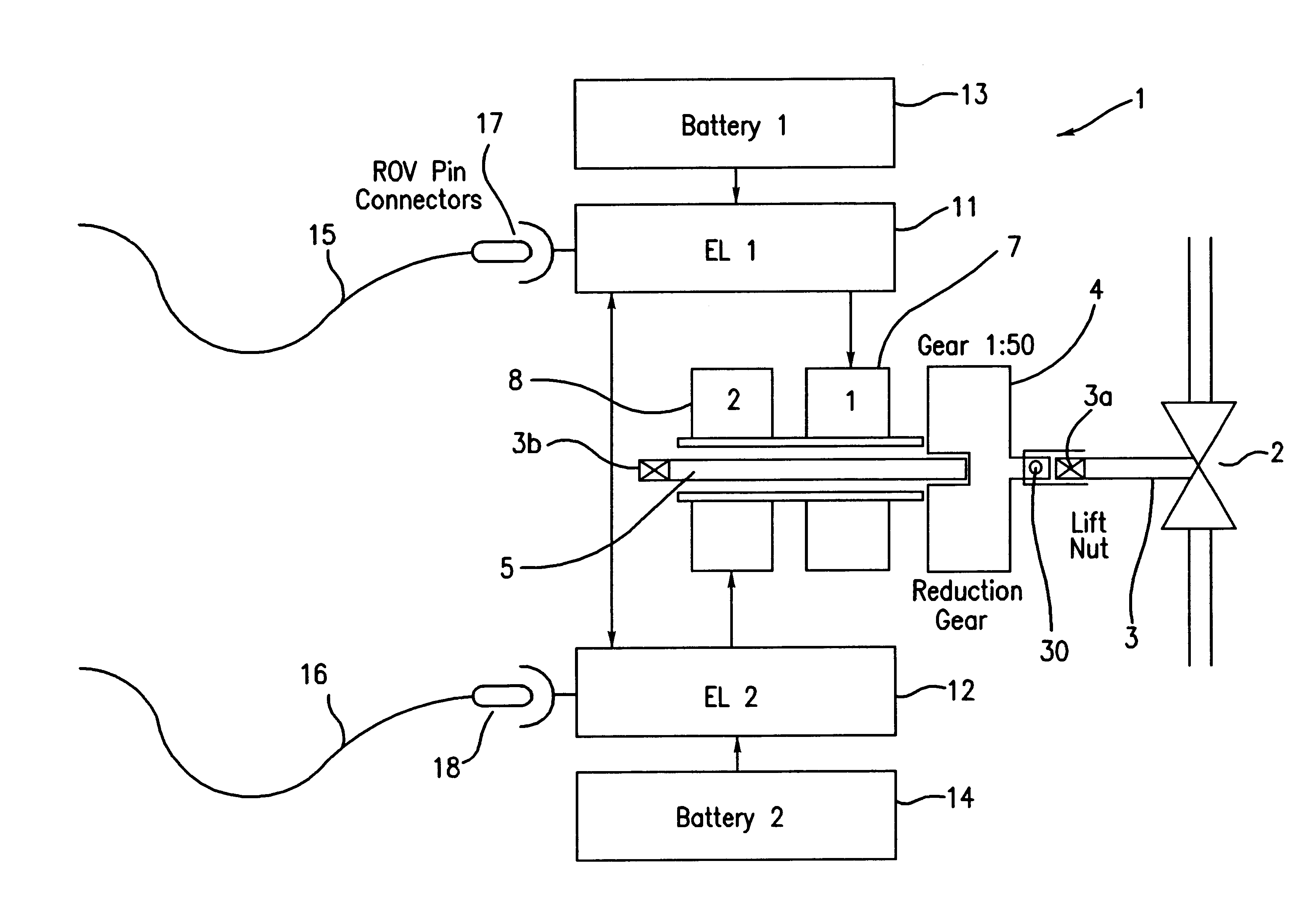
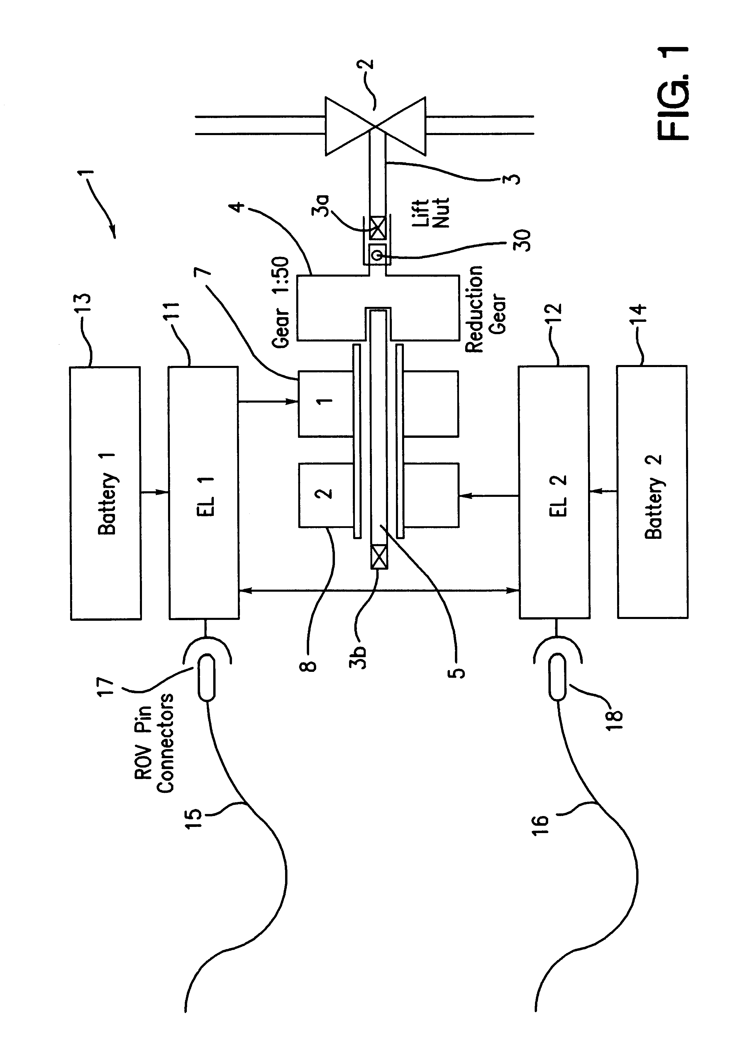
Referring firstly to FIG. 1, a valve 2 is operated by an electric actuator 1. The valve may as an example be a conventional gate valve with a valve spindle 3. The valve spindle 3 is at one end equipped with a coupling 3a. The end coupling may include a rotary to linear converter, when the valve is a sliding type valve. The end coupling is designed with an interface allowing it to be rotated by a standard tool of a remotely operated underwater vehicle (ROV), usually referred to as a manual override. This allows the valve to be operated even if the gearbox and motor has been decoupled from the valve spindle. The output shaft 30 of a reduction gear 4 has a corresponding interface.

Into the gear input side is a drive shaft 5 that is the output shaft of an electric motor 7, 8. The driveshaft 5 runs through the motor and has at its end 3b an interface, similar to the above, allowing manual override of the valve by using an ROV. The output shaft of the reduction gear may comprise a momentum...


PUM


Abstract

An actuator system for actuating a valve in a subsea environment comprises a valve spindle that is arranged to be coupled to an electric motor. To provide for power to the motor, at least one local electrical storage unit is provided. The system also includes a control unit comprising switching means for controlling the power to the motor. The control unit includes an intelligent processor and is arranged to receive signals from external sensors measuring a number of external and internal parameters, The actuator is preferable housed in a modular cage for easy replacement.

Description

1. Field of the InventionThis invention relates generally to a system for the control of valves in a subsea environment. More particularly, this invention relates to a system for actuating valves in oil and gas production wells and methods for controlling actuation of such valves.2. The Prior ArtThe control of subsea valves constitutes an on-going concern of the petroleum industry due, in part, to the enormous monetary expense involved as well as the risks associated with environmental and safety issues. As the exploration for oil and gas moves into ever deeper waters, the problems (and expense) associated with such activities gets ever larger.Before describing the current state-of-the-art relative to such valve control systems and methods, a brief description will be made of the production system, per se, in need of control. Oil and gas that are produced in a well flows upward through the well tubing to a wellhead placed on the seabed. A so-called Christmas Tree is connected to the...

Claims


Application Information

Patent Timeline
Patent Type & Authority Patents(United States)
IPC IPC(8): E21B33/03E21B33/035F16K31/04
CPCE21B33/0355F16K31/04
Inventor JOHANSEN, JOHN A.MAGNUS, HEYN HALFDANALMEDAL, ROY
Owner KONGSBERG OFFSHORE
Why Eureka
Try Eureka