Eureka AIR delivers breakthrough ideas for toughest innovation challenges, trusted by R&D personnel around the world.

Imageable photoresist laminate

a photoresist laminate and photoresist technology, applied in the field of photoresist laminates, can solve the problems of difficult positioning of diazonium compositions, lack of adequate strength and durability of styrylpyridinium compositions for some applications, and insufficient storage stability of diazonium salts, etc., to achieve the effect of improving processability, surface modification, and photoimaging

Inactive Publication Date: 2003-08-12
IKONICS CORP
View PDF8 Cites 8 Cited by
  • Summary
  • Abstract
  • Description
  • Claims
  • Application Information

AI Technical Summary

Benefits of technology

The invention can be embodied in various structures. In one structure, the carrier layer is coated with a membrane layer, and the photosensitive layer is applied over the membrane layer. In another structure, a carrier layer is directly coated with the photosensitive layer. These laminate structures can have other functional layers to improve processability, photoimaging, or surface modification.

Problems solved by technology

In addition, some diazonium salts show inadequate storage and stability properties.
However, styrylpyridinium salt compositions usually do not change color to form a print out image, and are therefore often more difficult to position than diazonium compositions.
In addition, styrylpyridinium compositions often lack adequate strength and durability for some applications.
A further problem with both of these resin materials, and resin materials in general, is that they sometimes undergo blocking or bricking, in which multiple laminates adhere together during storage.
Such undesirable adherence can be a significant obstacle to storing and using the laminate materials.

Method used


Image

  • Imageable photoresist laminate
  • Imageable photoresist laminate
  • Imageable photoresist laminate

Examples


examples

The following specific examples are used to further illustrate the invention. These examples are merely illustrative of the invention and do not limit its scope. The mixtures were made by weighing each of the ingredients into a mixing vat. The ingredients were mixed using an overhead mixing system with a standard propeller. The resulting mixtures exhibited good film-forming and adhesive properties and were photoimageable.

Photosensitive laminates were formed using the compositions of Example 1 and comparative Example 2. Masks were prepared by exposing each laminate to a 20 watt blacklight source using a photopositive tool.

Drying

The masks were developed with warm water from a flat spray and then air dried after blotting the masks on a lint-free towel. The material from Example 1 dried 50 percent faster than the material from comparative Example 2 under conditions of 70.degree. to 80.degree. F. and a relative humidity of approximately 15 to 25 percent.

Adhesion to Carrier Sheet

After bot...


PUM

PropertyMeasurementUnit
thicknessaaaaaaaaaa
thickaaaaaaaaaa
thickaaaaaaaaaa

Abstract

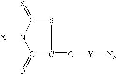
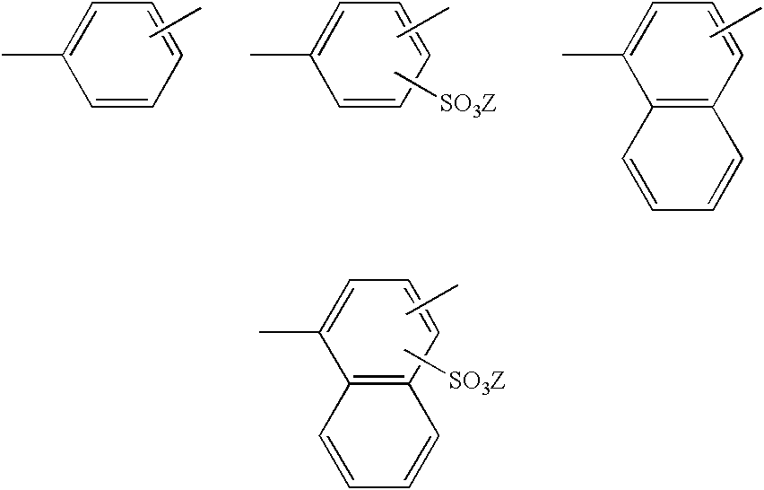
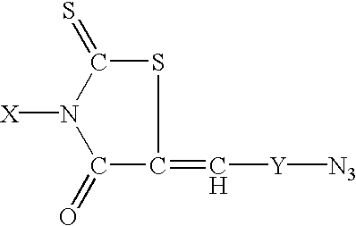
A photosensitive laminate structure including a carrier layer and a photosensitive layer is described. The photosensitive layer includes a polymeric photosensitive resin composition containing at least one cross-linkable unit represented by the formula:wherein X is an organic moity and Y is selected from the following group:wherein Z is selected from at least one of lithium, sodium, potassium, ammonium, monoalkylammonium, dialkylammonium, and tetraalkylammonium.

Description

The present invention relates to improved imageable photoresist laminates for use in abrasion etching applications. More particularly, the invention relates to durable imageable photoresist laminates containing a rhodanine-based crosslinkable resin.Photosensitive laminate structures have been used for many years to create imageable patterns useful for abrasion etching of substrate materials. The laminates contain photosensitive resins that are crosslinked by actinic radiation. Ultraviolet or visible light is used to imagewise expose these laminates and form a durable image in the laminate structure. The exposed images are subsequently developed to remove unexposed material. Thereafter the laminate is transferred to a substrate surface for selective surface modification, such as by abrasive etching using sandblasting techniques.One of the main materials used in photoresist laminates is photosensitive resins. Two commonly used types of photosensitive resins are those containing diazon...

Claims


Application Information

Patent Timeline
Patent Type & Authority Patents(United States)
IPC IPC(8): G03F7/012G03F7/008
CPCG03F7/012
Inventor JOHNSON, KYLEKOMATSU, TOSHIFUMIPETERSON, JEREMY WILLIAM
Owner IKONICS CORP
Why Eureka
Eureka Blog
Learn More