

Catalyzed diesel particulate matter exhaust filter
a technology of particulate matter and exhaust filter, which is applied in the direction of metal/metal-oxide/metal-hydroxide catalyst, machine/engine, arsenic compound, etc., can solve the problems of increased back pressure within the filter, increased pressure drop during use of the filter, and reduced engine efficiency
- Summary
- Abstract
- Description
- Claims
- Application Information
AI Technical Summary
Problems solved by technology
Method used
Image

Examples
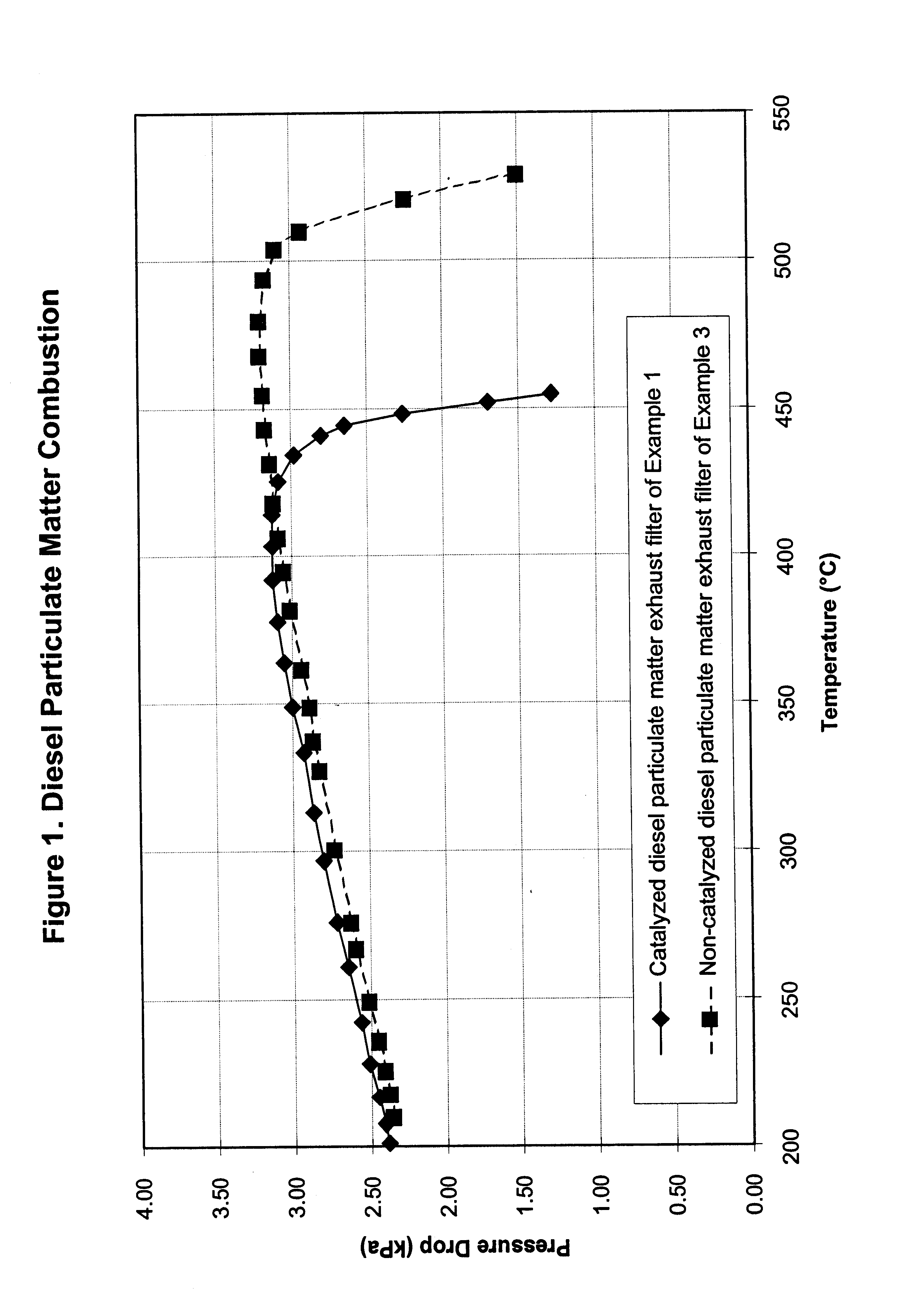
example 1
The Invention
A Corning cordierite ceramic monolith diesel particulate filter element (EX-80, 5.66 inch diameter and 6 inch length, 200 cells per square inch) was used for preparation of the example. The ceramic monolith element was dipped in 500 ml of an aqueous solution containing 15 g / l of magnesium in the form of magnesium nitrate, 20 g / l of vanadium in the form of vanadyl oxalate. After impregnation, any extra liquid was removed from the filter element by a vacuum suction. Following impregnation, the coated filter element was dried at 125.degree. C. for 2 hours and then calcined at 550.degree. C. for 3 hours. The magnesium vanadate loading was 300 grams per cubic foot (10.6 g / l). After cooling to room temperature, the filter element was dipped in a 500 ml aqueous solution of platinum sulfite acid (H.sub.4 Pt(SO.sub.4).sub.4) containing 10 g / l platinum. Extra liquid was removed by vacuum suction. Following impregnation, the coated filter element was dried at 125.degree. C. for 2 ...
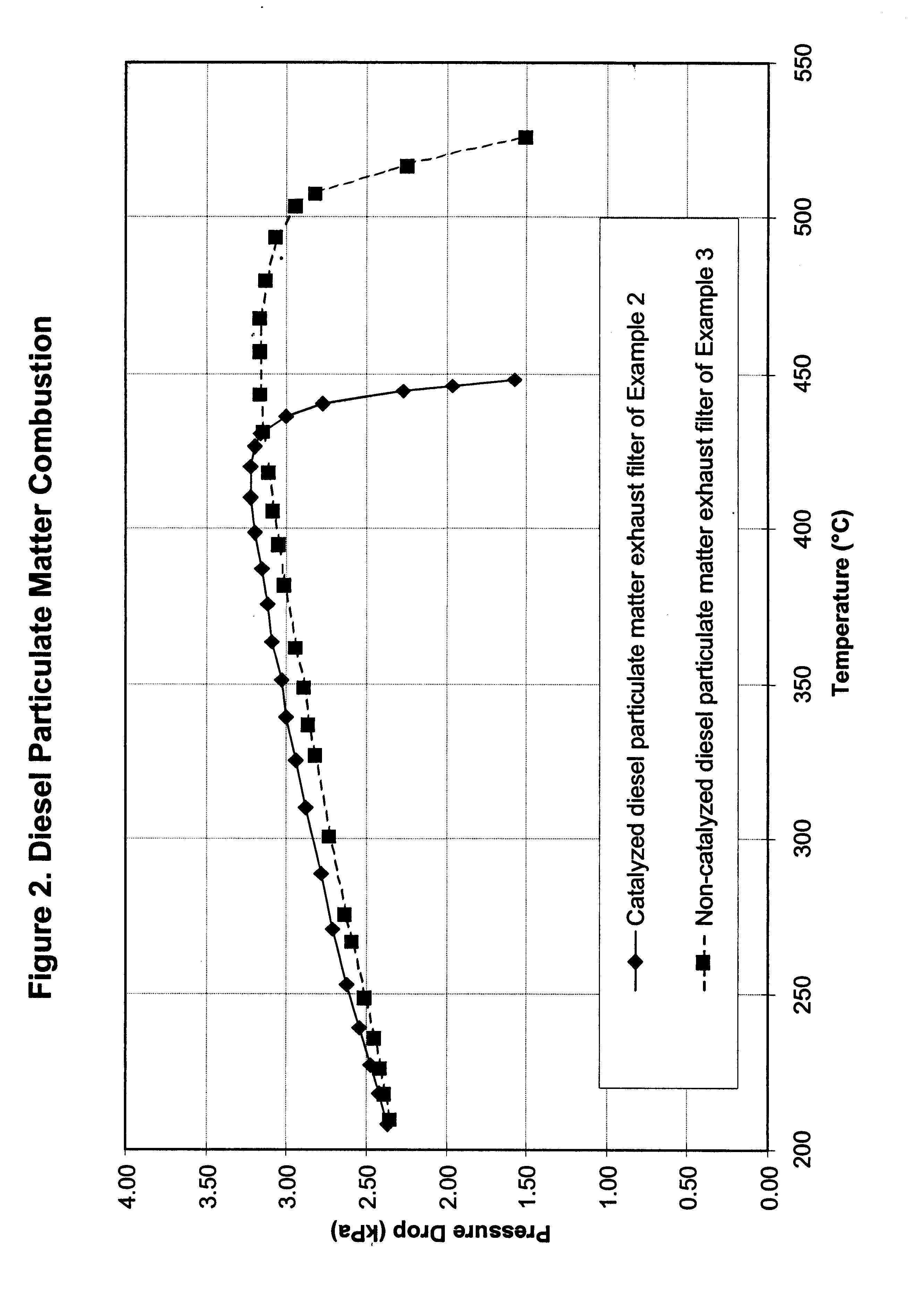
example 2
The Invention
A Corning cordierite ceramic monolith diesel particulate filter element (EX-80, 5.66 inch diameter and 6 inch length, 200 cells per square inch) was used for preparation of the example. An aqueous solution containing 15 g / l of magnesium as magnesium acetate, 20 g / l of vanadium as vanadium citrate and 10 g / l of platinum as platinum sulfite acid was prepared. The diesel particulate filter element was dipped into 500 ml of this solution. Any extra liquid was removed by a vacuum suction. The element was then subjected to drying at 125.degree. C. for 2 hours and calcination to 550.degree. C. for 3 hours. The final catalyst had a nominal platinum loading of 50 g / ft.sup.3 and a magnesium vanadate loading at 300 g / ft.sup.3. A core filter element sized with a 1.75 inch diameter and a 6 inch length was removed from the full size element and tested for regeneration. The same engine was used to test this filter element as is discussed in Example 1. The filter loaded with particulat...
example 3
Comparative Example
An uncatalyzed filter media element was prepared in the same manner as in Example 1. When the same tests were run on this uncatalyzed filter media, the burn off temperature of the diesel particulate matter was about 510.degree. C., as shown in FIGS. 1 and 2.
The results clearly show the enhanced performance of the filter coated with the catalytic material of the invention over a filter media element that was not coated with the catalytic material.
PUM
| Property | Measurement | Unit |
|---|---|---|
| temperature | aaaaa | aaaaa |
| temperature | aaaaa | aaaaa |
| temperature | aaaaa | aaaaa |
Abstract
Description
Claims
Application Information