

3D graphics rendering system for performing Z value clamping in near-Z range to maximize scene resolution of visually important Z components
- Summary
- Abstract
- Description
- Claims
- Application Information
AI Technical Summary
Benefits of technology
Problems solved by technology
Method used
Image

Examples
example graphics
Pipeline
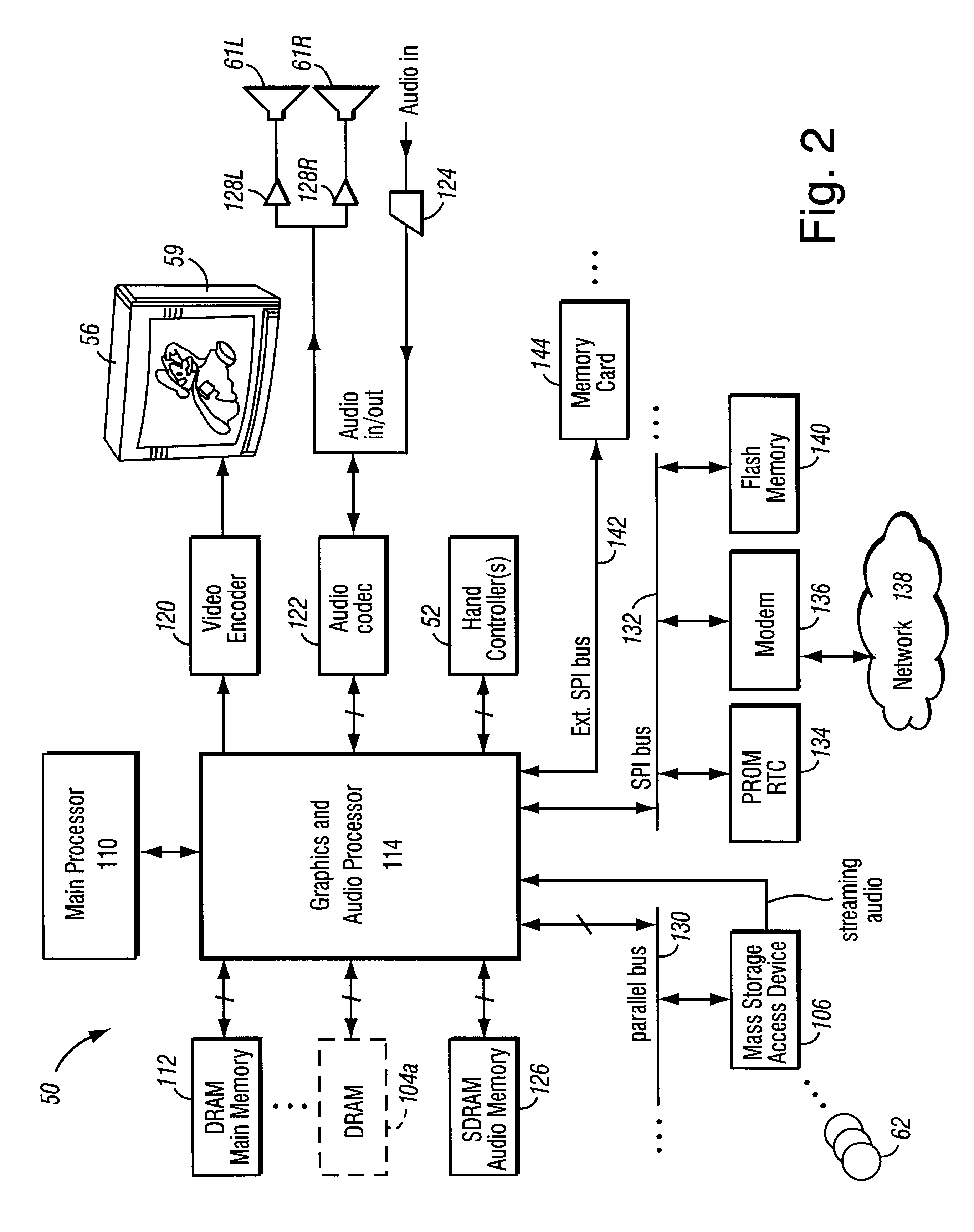
FIG. 4 shows a more detailed view of an example 3D graphics processor 154. 3D graphics processor 154 includes, among other things, a command processor 200 and a 3D graphics pipeline 180. Main processor 10 communicates streams of data (e.g., graphics command streams and display lists) to command processor 200. Main processor 110 has a two-level cache 115 to minimize memory latency, and also has a write-gathering buffer 111 for un-cached data streams targeted for the graphics and audio processor 114. The write-gathering buffer 111 collects partial cache lines into full cache lines and sends the data out to the graphics and audio processor 114 one cache line at a time for maximum bus usage.
Command processor 200 receives display commands from main processor 110 and parses them--obtaining any additional data necessary to process them from shared memory 112. The command processor 200 provides a stream of vertex commands to graphics pipeline 180 for 2D and / or 3D processing and rend...
example hardware implementation
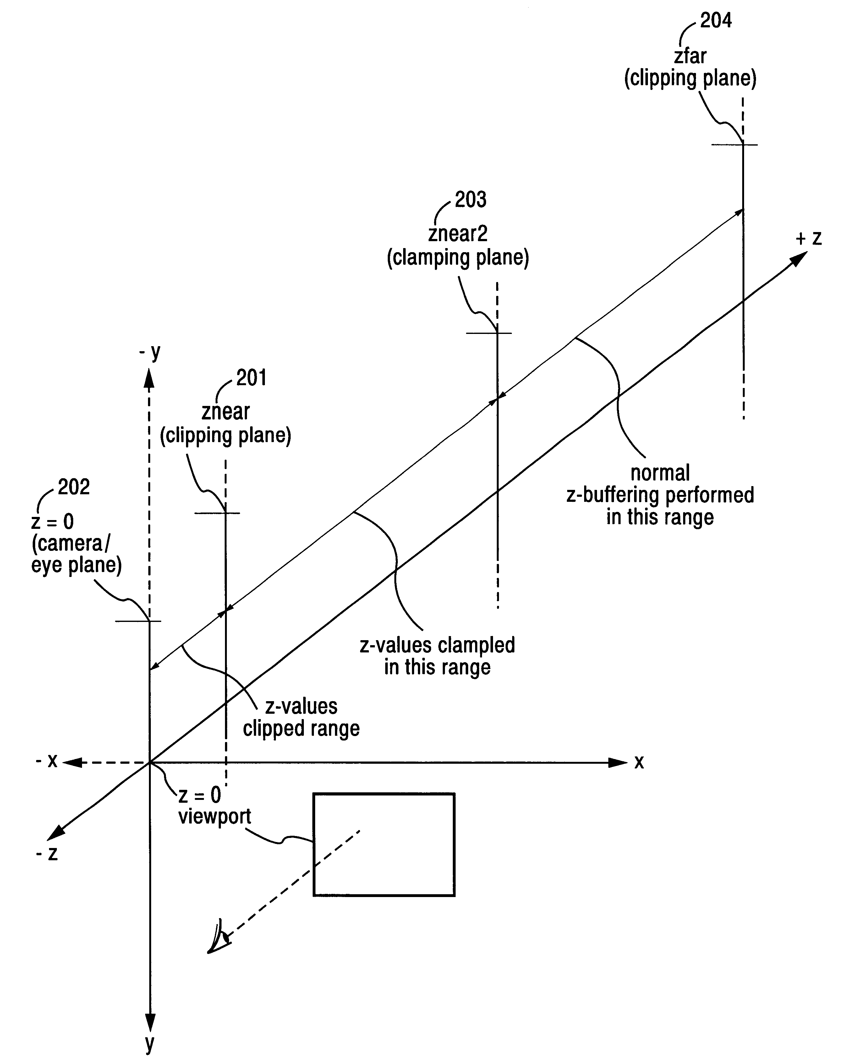
In example graphics pipeline 180, Transform Unit 300 includes both clipping plane logic circuitry and Z-compression logic circuitry. Because processing anti-aliased pixels requires more data to be stored in a limited size Z-buffer (i.e., embedded Frame Buffer 702), the Z value compression is performed in this example embodiment only when full scene anti-aliasing is enabled. Such Z-compression circuitry normally operates to compress a computed 24 bit Z attribute value to a 16 bit value. FIG. 8A shows example hardware logic circuitry that may be used for providing Z compression without providing any clamping of Z values. This example Z compression circuit essentially comprises a priority encoder 320 and a shifter 322 which performs compression on four 24 bit Z values, converting them to 16 bit values.
In the example implementation of graphics pipeline 180, a compression algorithm performs a type of reverse floating point encoding. Whereas conventional floating point notation clumps mos...
PUM
 Abstract
Description
Claims
Application Information