Adsorbents for low vapor pressure fluid storage and delivery

a technology of liquid storage and low vapor pressure, applied in the direction of colloidal chemistry, vessel construction details, separation processes, etc., can solve the problems of high cost, high cost, and high cost, and achieve the effect of reducing the risk of unwanted gas release from the cylinder, reducing the risk of gas leakage, and reducing the vapor pressure of the cylinder

Inactive Publication Date: 2003-09-16
ENTEGRIS INC
View PDF13 Cites 45 Cited by
  • Summary
  • Abstract
  • Description
  • Claims
  • Application Information

AI Technical Summary

Problems solved by technology

However, such conventional high-pressure gas cylinders are susceptible to leakage from damaged or malfunctioning regulator assemblies, as well as to rupture if internal decomposition of the gas leads to rapid increase of interior gas pressure in the cylinder.
These deficiencies pose a risk of unwanted bulk release of gas from the cylinder.
Such bulk release in turn can create very hazardous and even catastrophic conditions where toxic or otherwise hazardous fluids are involved, particularly during transportation and shipment of fluid cylinders when back-up scrubbing or other safety systems may not be present.
Although these sorbent materials of such pore size character are effective for reducing pressure of certain high vapor pressure fluids (e.g., AsH.sub.3, PH.sub.3, and BF.sub.3), they are not satisfactory for purpose of storing and delivering fluids of low vapor pressures (i.e. <200 psig at room temperature), especially the reactive fluids, for the following reasons.
First, such sorbent materials are chemically incompatible with low vapor pressure gases such as ClF.sub.3, WF.sub.6 and Br.sub.2, reacting with the gases to form unwanted byproducts.
Further, such conventionally employed sorbent materials, due to their respective pore size distributions, are oftentimes characterized by adsorption potentials that are too high.
They cannot effectively desorb low vapor pressure gases from the sorbent, and therefore are inadequate to deliver low vapor pressure gases to the tool under normal application conditions.
However, when the fluid storage and dispensing vessel of Wang et al. patent is used for liquefied gases, the fluid pressure regulator is susceptible to malfunction, because liquefied gases can easily enter the regulator and cause discharge pressure instability.
In such applications, the pressure instability incident to liquid ingress to the regulator compartment causes the occurrence of process perturbations that may render the product microelectronic device structure unsatisfactory or even wholly useless for its intended purpose.
Moreover, during the fluid delivery process significant cooling occurs when the liquefied gas is evaporated from the storage cylinder, due to the heat loss of vaporization.
The cooling will significantly reduce the vapor pressure of the liquefied gas, resulting in insufficient evaporation and slowing down gas flow from the cylinder.
However, the conventional sorbent materials have low thermal conductivities and are therefore ineffective for transfering heat to the liquefied gas inside the cylinder.
Insufficient heat transfer causes uneven distribution of thermal energy in different portions of the cylinder, i.e., overheating of the exterior of the cylinder and underheating of the interior of the cylinder.
The art has not found a solution to the above-described problems associated with low vapor pressure fluids or liquefied gases, with respect to sorbent materials having good sorptive affinity, good capacity loading characteristics, good chemical stability, good desorption characteristics, good thermal conductivity, or of liquid containment and occlusion from the regulator element in internal regulator-based fluid storage and dispensing systems.

Method used


Image

  • Adsorbents for low vapor pressure fluid storage and delivery
  • Adsorbents for low vapor pressure fluid storage and delivery
  • Adsorbents for low vapor pressure fluid storage and delivery

Examples


example 1

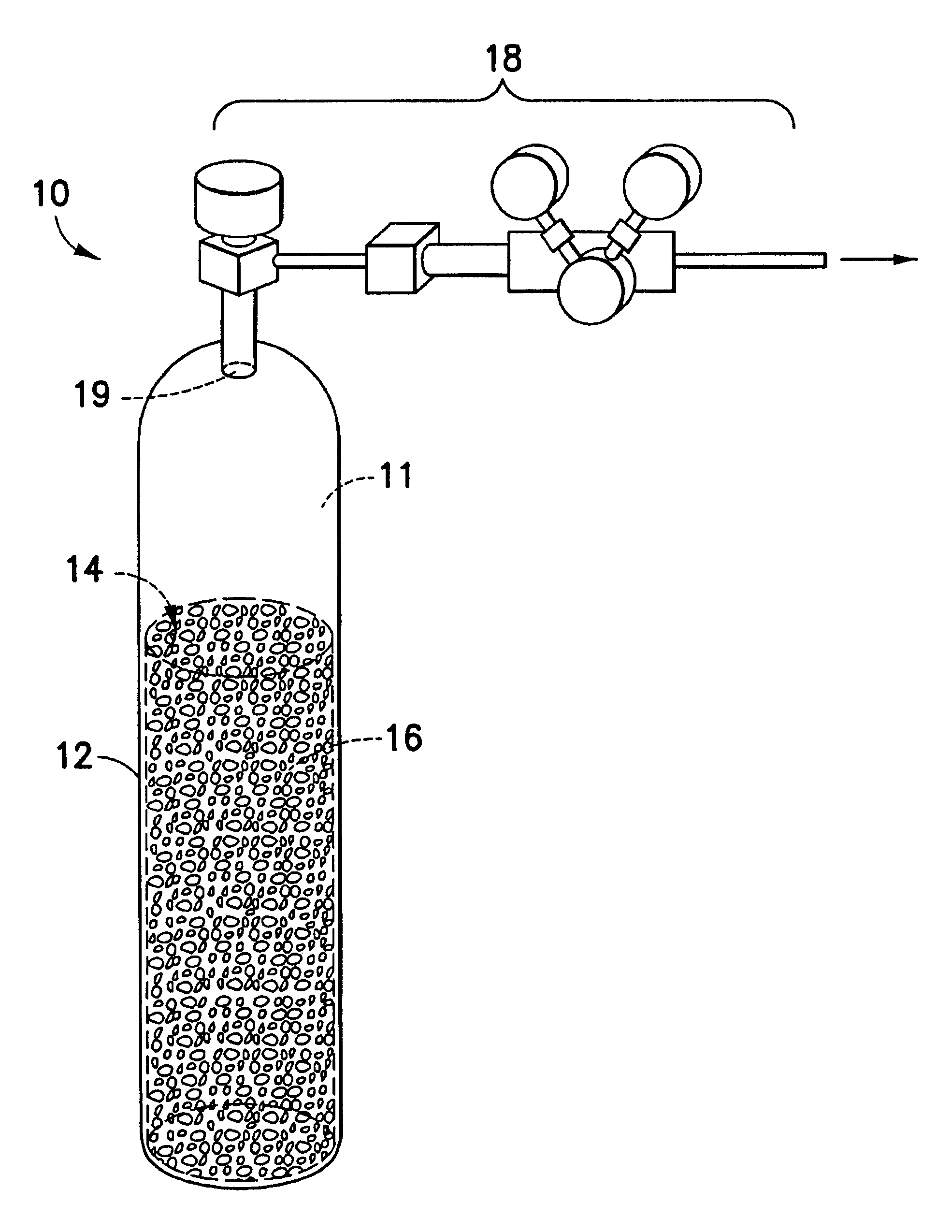
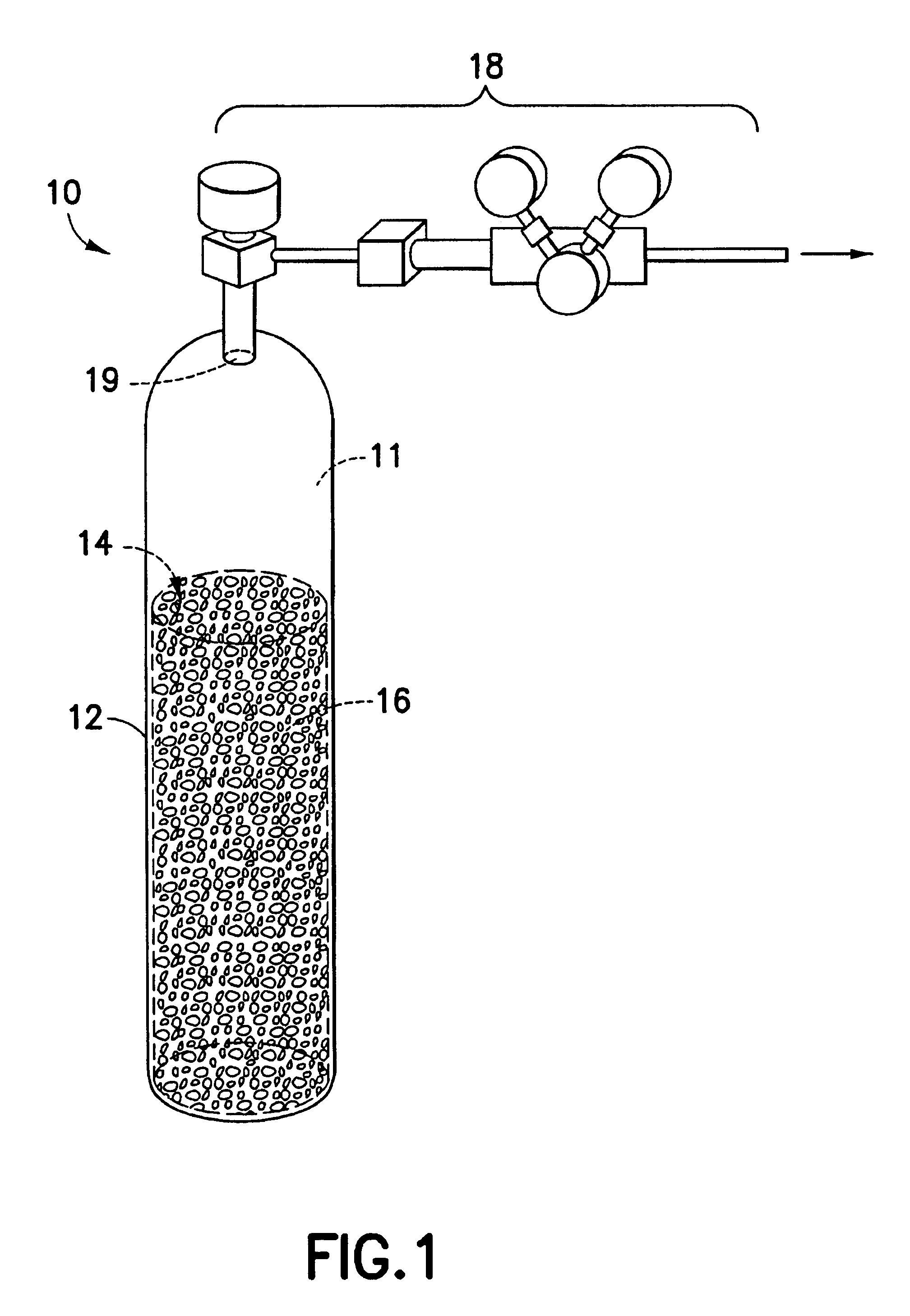
Tests were conducted to determine the sorbate storage capacities of two porous metal adsorbent materials. The first adsorbent is formed bysintering INCO.RTM. Type 210 nickel powder (commercially available from Inco Limited, Wyckoff, N.J., USA) and the second adsorbent was formed from INCOFOAM.RTM. porous nickel substrate (commercially available from Inco Limited, Wyckoff, N.J. USA). Eachadsorbent was placed in a 7 m available from Swagelok Company, Solon, Ohio, USA), which was then positioned in a in stainless steel container having an interior volume of 50 ml.

Isopropanol (hereinafter "IPA") was added to the sorbent. The total weight of IPA liquid added was recorded, and the container was continuously monitored for detection of any IPA liquid dripping. As soon as dripping of liquid from the container was detected, addition of IPA liquid was immediately terminated, and the total weight of IPA liquid previously added was recorded. The total weight of the added IPA liquid indicated the...

example 2

Similar tests for adsorbents formed of INCO.RTM. Type 210 nickel powder (commercially available from Inco Limited, Wyckoff, N.J., USA) and of INCOFOAM.RTM. porous nickel substrate (commercially available from Inco Limited, Wyckoff, N.J., USA) were conducted to determine the storage capacities of such adsorbents for Br.sub.2 gas.


PUM


Abstract

The invention relates to a fluid storage and delivery system utilizing a porous metal matrix that comprises at least one Group VIII metal or Group IB metal therein. In one aspect of the invention, such porous metal matrix forms a solid-phase metal adsorbent medium, characterized by an average pore diameter of from about 0.5 nm to about 2.0 nm and a porosity of from about 10% to about 30%. Such solid-phase metal adsorbent medium is particularly useful for sorptively storing and desoprotively dispensing a low vapor pressure fluid, e.g., ClF3, HF, GeF4, Br2, etc. In another aspect of the invention, such porous metal matrix forms a solid-phase metal sorbent, characterized by an average pore diameter of from about 0.25 mum to about 500 mum and a porosity of from about 15% to about 95%, which can effectively immobilize low vapor pressure liquefied gas.

Description

BACKGROUND OF INVENTION1. Field of InventionThe invention relates to a fluid supply systems, to a solid-phase adsorbent material useful for storing and dispensing fluids of low vapor pressure, and to a solid-phase sorbent material useful for storing and dispensing liquefied fluids.2. Description of the Related ArtIn a wide variety of industrial processes and applications, there is a need for a reliable source of process fluids. Such process and application areas include, but are not limited to, semiconductor manufacturing, ion implantation, manufacture of flat panel displays, medical intervention and therapy, water treatment, emergency breathing equipment, welding operations, space-based delivery of liquids and gases, etc.Conventionally, processing fluids are supplied for commercial applications by means of high-pressure cylinders containing compressed processing fluids. However, such conventional high-pressure gas cylinders are susceptible to leakage from damaged or malfunctioning ...

Claims


Application Information

Patent Timeline
Patent Type & Authority Patents(United States)
IPC IPC(8): F17C11/00
CPCF17C11/00F17C11/007F17C2205/0338F17C2205/0391F17C2270/0518Y02E60/321Y10S502/526Y10S95/90Y02E60/32
Inventor WANG, LUPINGNEUGOLD, DOUG
Owner ENTEGRIS INC
Why Eureka
Try Eureka