Semiconductor device having desired gate profile and method of making the same

a technology of magnetic resonance and gate profile, applied in the field of control gates, can solve the problems of limited scalability, limited alignment tolerance, mechanical techniques, etc., and achieve the effect of reducing the electrical characteristics of the memory device, reducing the scalability, and reducing the scalability

Inactive Publication Date: 2003-09-16
SAMSUNG ELECTRONICS CO LTD
View PDF12 Cites 107 Cited by
  • Summary
  • Abstract
  • Description
  • Claims
  • Application Information

AI Technical Summary

Problems solved by technology

Below the half-micron design rule, scalability is limited by photolithographic resolution attainable during manufacturing and by alignment tolerances of masks used during production.
Alignment tolerances are, in turn, limited by mechanical techniques employed to form masks and the techniques used to register these masks between layers.
This phenomenon is undesirable because it degrades the electrical characteristics of the memory device.
As such, alignment errors associated with forming the isolation structure and memory cells aggregate to induce mis-alignment, which may result in failure of the device.
Even though self-aligned STI processes have an advantage of simultaneously forming floating gates and active regions, there is still a drawback because the aspect ratio of gaps formed in the process is increased, which is likely to form seams or voids wit

Method used


Image

  • Semiconductor device having desired gate profile and method of making the same
  • Semiconductor device having desired gate profile and method of making the same
  • Semiconductor device having desired gate profile and method of making the same

Examples


second embodiment

FIGS. 4A and 4B are sectional views for showing a method for manufacturing a non-volatile memory device according to the present invention.

first embodiment

Referring to FIG. 4A, in the same manner as in the first embodiment, a gate oxide layer 101, a first silicon layer 103, a buffer oxide layer 105, and a stopping layer 107 are sequentially formed on substrate 100.

Referring to FIG. 4B, using a photo mask for defining a floating gate, a photoresist pattern 160 is formed on the stopping layer 107 as in the first embodiment. Then, the stopping layer 107, the buffer oxide layer 105, the first silicon layer 103, and the gate oxide layer 101 are patterned by using the photoresist pattern 160 as an etch mask so that a pattern structure formed by the stopping layer pattern 108, the buffer oxide layer pattern 106, the first silicon layer pattern 104, and the gate oxide layer pattern 102 is formed.

Next, substrate 100 is etched to form a trench 109, and an ashing or a strip process is performed to remove the photoresist pattern 160.

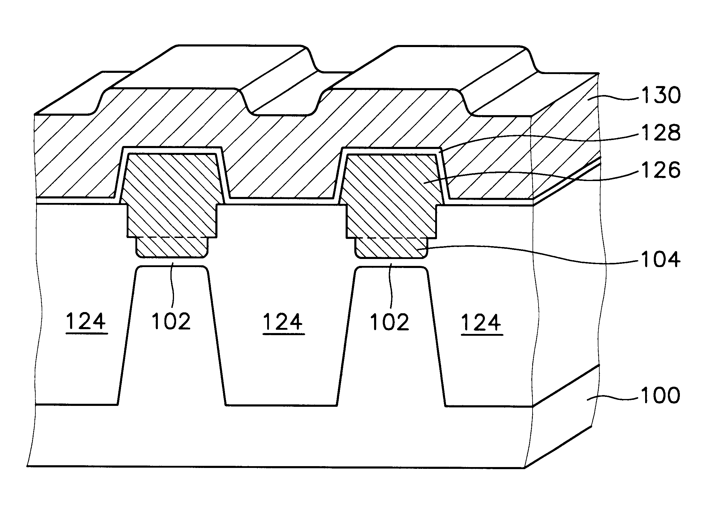
Thereafter, the processes shown in FIGS. 2C to 2I of the first embodiment are performed thereby providing a floatin...


PUM


Abstract

In a method of manufacturing a non-volatile memory or other semiconductor device, a control gate made of conductive material is formed in a more uniform fashion. The method includes forming a silicon layer on a buffer oxide layer on a semiconductor substrate. After forming the buffer oxide layer, a stopping layer is formed. The control gate of conductive material, such as a floating gate in an EEPROM memory device, is provided by patterning the silicon layer, gate oxide layer, and the substrate, and then, a trench is formed in the upper portion of the substrate. Uniformity is achieved by oxidizing the sidewalls of the trench to create bird's beaks at both upper and lower portions of the control gate material. Then, a field oxide layer that fills up the trench is formed. Because bird's beaks are evenly formed at both upper and lower portions of the control gate material during oxidation of the sidewalls of the trench, it is formed in a more uniform fashion since achieves uniformity is attained by preventing the sidewalls of the floating gate, for example, from having positive slopes.

Description

1. Field of the InventionThe present invention relates to a control gate, such as a floating gate in a memory device, and a method of making the same, but more particularly to a self-aligned shallow trench isolation technique that simultaneously forms a gate and an active region thereof.2. Description of the Related ArtDuring the manufacture of memory devices, the packing density of cells is primarily determined by the layout of cells within the array and the physical dimensions of the cells themselves. Below the half-micron design rule, scalability is limited by photolithographic resolution attainable during manufacturing and by alignment tolerances of masks used during production. Alignment tolerances are, in turn, limited by mechanical techniques employed to form masks and the techniques used to register these masks between layers. Because alignment errors accumulate during multi-stage fabrication, it is preferable to use as few masks as possible. Fewer masks minimizes the likeli...

Claims


Application Information

Patent Timeline
IPC IPC(8): H01L21/02H01L21/28H01L21/70H01L21/8247H01L27/115
CPCH01L21/28273H01L27/115H01L27/11521H01L29/40114H10B69/00H10B41/30
Inventor KIM, MINKIM, SUNG-TAE
Owner SAMSUNG ELECTRONICS CO LTD
Why Eureka
Try Eureka