Supply of power to primary conductors

a technology of primary conductors and supply voltage, which is applied in the direction of inductance with magnetic cores, transmission, cores/yokes, etc., can solve the problems of high voltage required difficult to drive parallel-tuned tracks long, and limit the voltag

Inactive Publication Date: 2003-09-16
AUCKLAND UNISERVICES LTD
View PDF8 Cites 42 Cited by
  • Summary
  • Abstract
  • Description
  • Claims
  • Application Information

AI Technical Summary

Benefits of technology

In a still further a related aspect the invention provides apparatus as previously described, wherein the apparatus comprises at least one transconductance pi network connected to each primary trackway, the at least one network being provided with at least one set of additional reactive components capable as a group of being controllably switched into or out of the network circuit from a first set of components capable of determining a first current, to a second set of components, capable of determining a second current, so that the circulating current to be supplied from the output of the network into each primary trackway can be controlled from time to time and so

Problems solved by technology

When inductive power transfer is to be applied to systems including relatively long primary inductive pathways or tracks, high-frequency alternating currents at the high voltage that is required to drive parallel-tuned tracks become rather difficult to generate in a practicable manner.
The high voltage is required in order to insert sufficient current into the track, given an unavoidable track inductance.
It is difficult to drive a long, parallel-tuned track because (apart from safety and insulation considerations) there are finite limits to the vo

Method used


Image

  • Supply of power to primary conductors
  • Supply of power to primary conductors
  • Supply of power to primary conductors

Examples


example 1 (fig.2)

EXAMPLE 1 (FIG. 2)

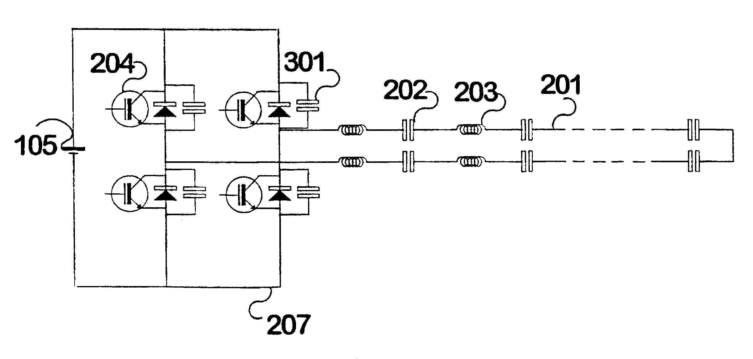
This example comprises a full-bridge switching circuit in which each arm of the bridge is occupied by a switch and no resonating components exist within the circuit. A circuit illustrating the principle is illustrated in FIG. 2. Our preferred switches are insulated-gate base transistors (IGBTs) and our preferred operating frequency is generally at about 10 kHz, although IGBT devices are becoming increasingly capable of high-speed operation. The series resonant track is indicated at 201 and comprises a series of series capacitors 202, in series with track inductance 203 (here the track inductance is shown as a lumped symbol).

In the simple form at least, each of the four switches (204, 205, 206, 207) is operated in a 180 degree conduction angle, and current passes alternately from a DC supply 105 through 204, then through the track, then 207, or from the DC supply though 205, through the track in the opposite direction, and then 206, to reach the DC return path. Diod...

example 2 (fig.3)

EXAMPLE 2 (FIG. 3)

Zero-Voltage Switching (Soft switching)

The prior-art half-bridge resonant converter of FIG. 1 could easily be controlled so as to switch at each zero-voltage instant--a feature which minimises switching losses and the generation of interference. The circuit of FIG. 2 assumed that zero-voltage switching was not intended. We have found that if the circuit of FIG. 2 is driven at a frequency slightly above the resonant frequency of the track and if we also include a small capacitor 301 across each switching device, as shown in FIG. 3, it is then possible to take advantage of the inductive impedance of the track in order to attain zero-voltage switching. A residual track inductance discharges the parallel capacitors during switching transitions. The small capacitors are each of the order of 100 to 1000 nF (example capacitor used at 15 kHz--where switches are 300 A, 1200 V IGBTs are WIMA 0.22 .mu.F FKP1). Of course the "lock-out" time between switching the top and bottom...

example 3 (fig.5)

EXAMPLE 3 (FIG. 5)

While the full-bridge converters described above have some control advantages, they also suffer from the significant drawback that the full circulating current passes through the switching devices. If a half-bridge power supply could be modified so that it can provide current to a series-compensated track, one would expect that the switching devices would be much more lightly loaded. Furthermore the drive current provided by the previous example is relatively rich in harmonics. Even though the higher harmonics see a higher impedance, at least part of those higher harmonics are radiated.

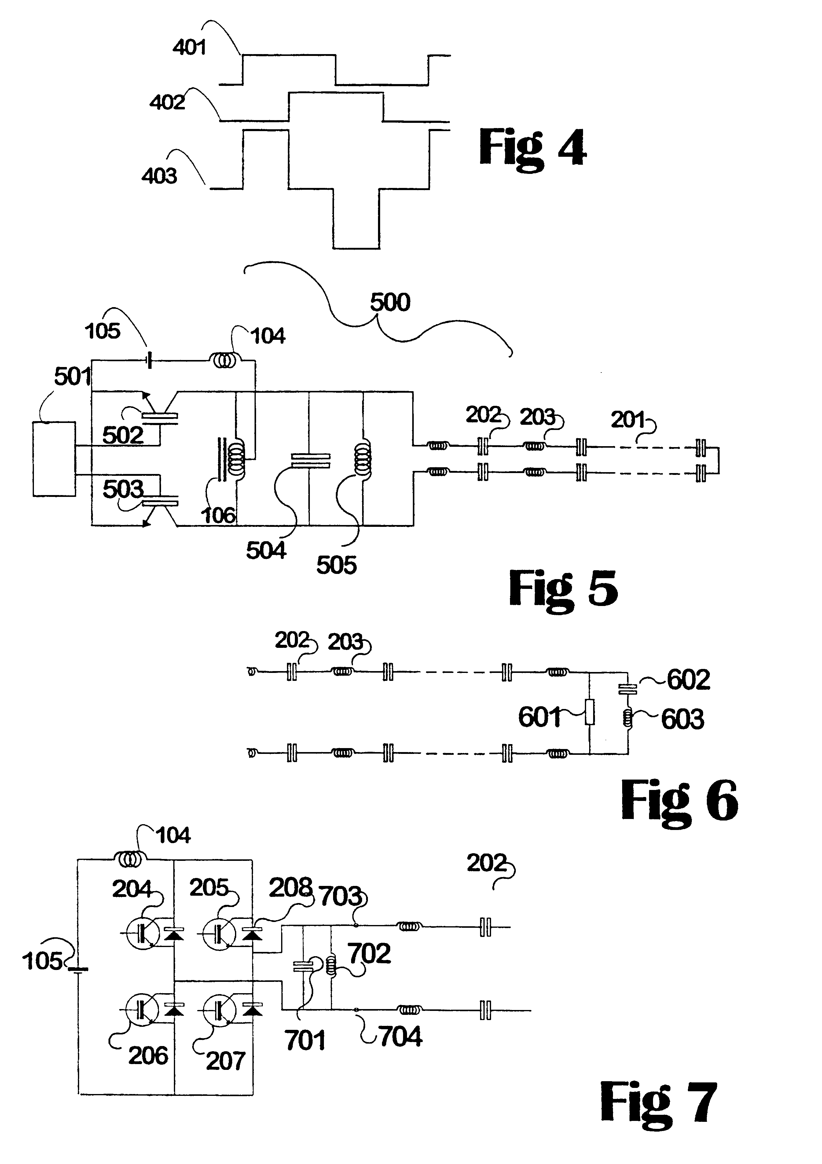
In FIG. 5, the circuit 500 drives a series resonant primary inductive loop 20; including lumped capacitors 202 and distributed (track) inductances 203 from a half-bridge pair of switches 502, 503 using an internal resonant circuit comprising an inductor 505 and capacitor 504 as a resonant circuit across which the loop is connected. The values of the components may be entirely determi...


PUM


Abstract

Apparatus for providing effective amounts of high-frequency AC power to a long primary trackway (1102), used for inductive power transfer includes transconductance-pi filters (1105) for deliberate mismatching; resulting in independence of current flow and track impedance. These cause the source (1101) to appear as a voltage source and the trackway to appear as a low reactance. Shorting the output (1106) cuts the connected trackway from power without harm. The filter can cause a voltage step-up so driving a longer track. Track termination apparatus is disclosed that acts as a short circuit at only the operating frequency while terminating the track at its characteristic impedance otherwise. Half-bridge and full-bridge power supplies (1101) are described for providing effective amounts of high-frequency AC power to a long primary trackway used for inductive power transfer.

Description

This invention relates to the supply of power to the trackway conductors forming the primary circuit of an inductive power supply system; in particular this invention relates to the supply of power to the trackway conductors connected in a series resonant circuit which comprises the primary circuit of an inductive power supply system capable of distributing inductive power over a distance.An inductive power transfer system generally comprises (a) a generator of alternating current, (b) one or more conductors carrying the alternating current as tracks (the "primary inductive pathway") to one or more consumers, (c) a space carrying an alternating magnetic flux as a consequence of current flow within the conductor(s), (d) a pickup means (the "secondary winding"), which intercepts a part of the magnetic flux, and (e) power consuming means. Systems originating from our developments have been characterised by inclusion of: (f) an operating frequency generally above 10 kHz, (g) a tuned, re...

Claims


Application Information

Patent Timeline
IPC IPC(8): H02J5/00H02J17/00B60M7/00H01F3/14H01F17/06H04B5/00
CPCH02J5/005H04B5/00H01F3/14H01F17/06H04B5/0012H04B5/0037H02J50/402H02J7/00309H02J50/70H02J50/12H02J50/005H02J3/06
Inventor BOYS, JOHN TALBOT
Owner AUCKLAND UNISERVICES LTD
Why Eureka
Try Eureka