Method for selecting combination of host material and light-emitting material, and organic light-emitting device using combination selected thereby

a technology of light-emitting devices and host materials, which is applied in the manufacture of electrode systems, electric discharge tubes/lamps, and discharge tubes luminescnet screens, etc., can solve the problems of poor light-emitting efficiency, and inability to meet the requirements of us

Inactive Publication Date: 2003-09-30
FUJIFILM HLDG CORP +1
View PDF9 Cites 39 Cited by
  • Summary
  • Abstract
  • Description
  • Claims
  • Application Information

AI Technical Summary

Benefits of technology

An object of the present invention is to provide a method for easily selecting a preferred combination of a host material and a light-emitting material to be used for a light-emitting layer of an organic light-emitting device, and to provide an organic light-emitting device containing the combination selected by the method to exhibit a high light-emitting efficiency.
As a result of intense research in view of the above object, the inventor has found that a preferred combination of a host material and a light-emitting material can be easily selected by evaluating light-emitting properties of a mixture film containing a light-emitting material and a host material without production of organic light-emitting devices using different materials from each other. The present invention has been accomplished by the finding.
By the method of the present invention, a combination of a host material and a light-emitting material such that the organic light-emitting device using the combination exhibits easy energy transfer and high light-emitting efficiency can be easily selected from host materials such as carbazole compounds (CBP, etc.) and light-emitting materials such as organic heavy metal complexes (Ir(ppy).sub.3, etc.). The steps in the method will be described in detail below.
The solvent for the solution containing the host material and the light-emitting material is not particularly limited if only it can dissolve both of the host material and the light-emitting material. The solvent may be dichlorethane, chloroform, toluene, etc. When the solution is applied to the substrate by dropping, the amount of the applied solution per the surface area thereof is too large to dry the solution in a short time, whereby the host material and the light-emitting material tend to be separately deposited to provide the mixture film where the materials are not mixed uniformly in molecular level. Thus, it is preferable that the solution is applied to the substrate by a spin-coating method, a bar-coating method, a roll-coating method, a dip-coating method, etc. from the viewpoints of drying the applied solution in a short time not to cause separate deposition of the host material and the light-emitting material. Among the methods, particularly preferred is a spin-coating method capable of rapidly and precisely applying the solution to the substrate.

Problems solved by technology

However, the organic light-emitting devices are inferior in light-emitting efficiency to inorganic LED devices and fluorescent tubes, thereby being far from practicable.
Therefore, the organic light-emitting devices utilizing the fluorescence can practically apply only 25% of the excitons, thereby inevitably being poor in the light-emitting efficiency.
This is because long period of time is necessitated to evaluate the materials.
Since light-emitting mechanism of the organic light-emitting device, in particular, such that utilizes triplet excitons, has not yet been sufficiently solved, the materials must be evaluated after practically producing the device.
The production of the device requires a plurality of processes including vacuum deposition, so that a plurality of the devices cannot be produced at the same time in the same apparatus.

Method used


Image

  • Method for selecting combination of host material and light-emitting material, and organic light-emitting device using combination selected thereby
  • Method for selecting combination of host material and light-emitting material, and organic light-emitting device using combination selected thereby
  • Method for selecting combination of host material and light-emitting material, and organic light-emitting device using combination selected thereby

Examples


example 1

A glass substrate of 2.5 cm.times.2.5 cm in size and 0.5 mm in thickness was washed with ultrasonic wave in isopropylalcohol. Then, PMMA acetone solution (5 weight %) was spin-coated on this washed glass substrate and dried, to provide an inert polymer layer. The spin-coating was carried out at 800 rpm for 20 seconds.

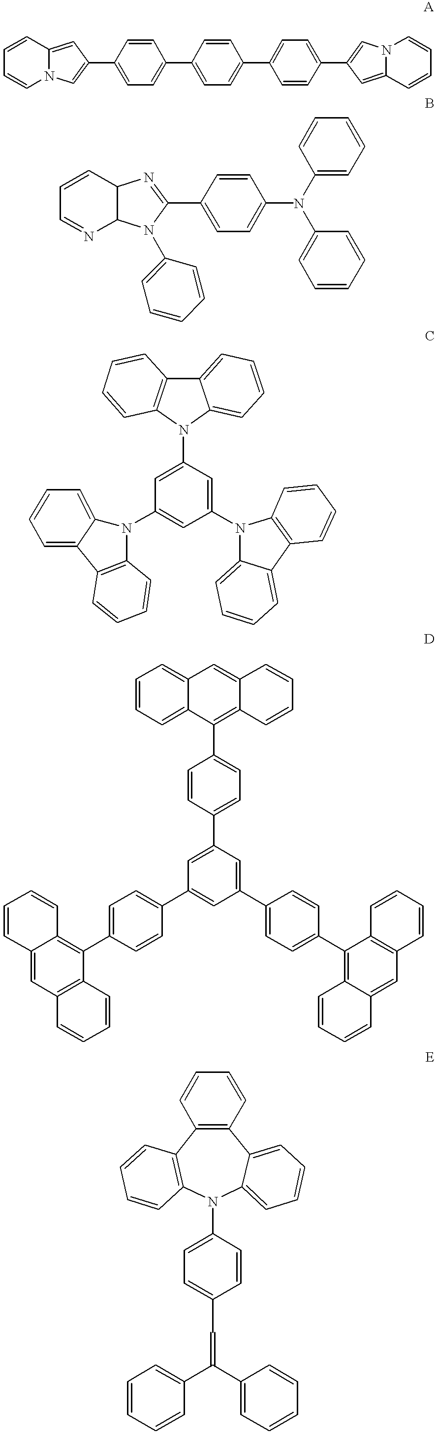
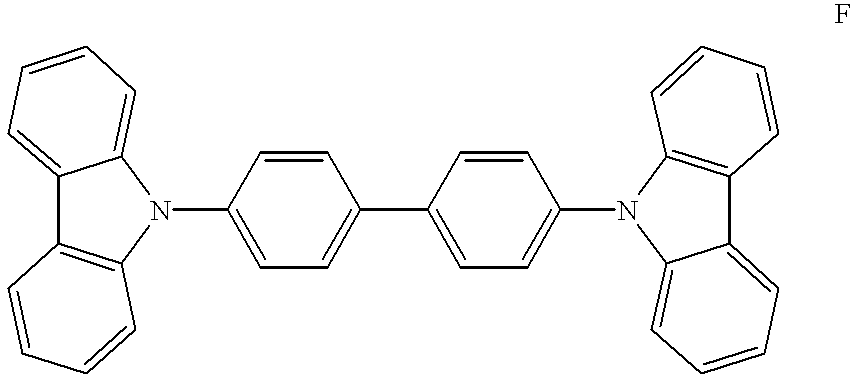
1 mg of light-emitting material I (tris(2-phenylpyridine)-iridium complex, Ir(ppy).sub.3) and 15 mg of host material A shown below were dissolved in 5 ml of dichloroethane. The resultant solution was spin-coated on the above-described inert polymer layer at 500 rpm for 20 seconds and dried to prepare a mixture film of IA. Further, these steps were repeated except for using each of host materials B to F shown below instead of the host material A, to prepare mixture films of IB to IF, respectively. Incidentally, for example, "IA" means the combination of the light-emitting material I and the host material A. ##STR1## ##STR2##

The mixture films of IA to IF were measured wit...

example 2

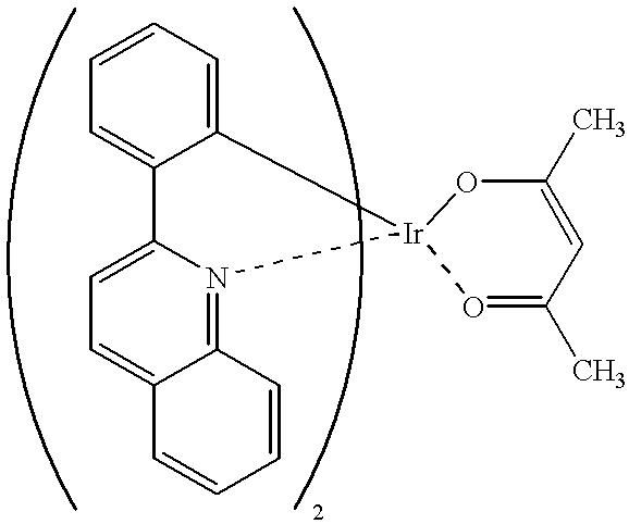
The combinations of the light-emitting material II shown below and each host material E and F, IIE and IIF were evaluated in the same manner as Example 1, respectively. The results were shown in Table 2.

As shown in Table 2, it was found by the method of the present invention that the host material F was suitably used in combination with the light-emitting material II.

As described in detail above, a preferred combination of a host material and a light-emitting material to be used for a light-emitting layer of an organic light-emitting device can be easily selected by a method of the present invention. Further, an organic light-emitting device exhibiting high light-emitting efficiency can be obtained by using the preferred combination of the host material and the light-emitting material selected by the method.


PUM


Abstract

A method for selecting a combination of a host material and a light-emitting material to be used for a light-emitting layer of an organic light-emitting device, involving the steps of: (a) disposing a mixture film containing a host material and a light-emitting material on a substrate; and (b) evaluating the mixture film with respect to light-emitting properties while irradiating a light that is absorbed by the host material to the mixture film. An organic light-emitting device with a light-emitting layer containing the combination of the host material and the light-emitting material selected by the method is also provided.

Description

The present invention relates to a method for selecting a combination of a host material and a light-emitting material to be used for a light-emitting layer of an organic light-emitting device, and an organic light-emitting device using the combination of the host material and the light-emitting material selected by the method.Organic light-emitting devices generally comprise a light-emitting layer of a light-emitting material disposed between an electron-injecting electrode (negative electrode) and a hole-injecting electrode (positive electrode). Electrons and holes are injected into the light-emitting layer and recombined therein to produce excitons, and the excitons are deactivated so that the light-emitting material emits fluorescence and / or phosphorescence. C. W. Tang, et al. have demonstrated in 1987 that an organic light-emitting device where a positive electrode, an organic hole-transporting layer, a light-emitting layer, an organic electron-transporting layer and a metal ne...

Claims


Application Information

Patent Timeline
Patent Type & Authority Patents(United States)
IPC IPC(8): H01L51/40H01L51/05H01L51/50H05B33/10
CPCH01L51/0003H01L51/5012H01L51/5016H10K71/12H10K50/11H10K2101/10
Inventor TAKEMATSU, MASAKAZUMISHIMA, MASAYUKI
Owner FUJIFILM HLDG CORP
Why Eureka
Try Eureka