Power inverter for driving alternating current loads

a technology of alternating current and inverter, which is applied in the direction of electric variable regulation, process and machine control, instruments, etc., can solve the problems of runaway condition, bridge inverter requires lower voltage switches but is harder to drive, and push-pull switching has never reached the efficiency of a bridge operation, etc., to prolong the life of the driven lamp

Inactive Publication Date: 2003-09-30
LUMINOPTICS
View PDF7 Cites 87 Cited by
  • Summary
  • Abstract
  • Description
  • Claims
  • Application Information

AI Technical Summary

Benefits of technology

FIG. 6 is the software flow chart of the most desirable way for a ballast to start a fluorescent lamp. The application of this starting process as shown on this flow chart is not possible in present day ballasts and can greatly prolong the life of the driven lamp.

Problems solved by technology

However this configuration requires much higher voltage switching devices than the bridge method, in addition push-pull switching has never reached the efficiency of a bridge operation.
Bridge inverters require lower voltage switches but are harder to drive as one of the switches is not connected to the common bus.
When resonance is employed, a runaway condition can occur if proper feedback is not introduced to control the frequency.
However, it is not exceptionally tolerant of variations in loads and input voltages.
The problems that have arisen with this type of circuit involve out of the ordinary conditions where the load is suddenly interrupted by lamp failure or breakage, or where a lamp will not start due to age, temperature, or other reasons.
Up to now this has involved a very complex amount of logic circuitry and extra expensive design of the resonant components.

Method used


Image

  • Power inverter for driving alternating current loads
  • Power inverter for driving alternating current loads
  • Power inverter for driving alternating current loads

Examples


Embodiment Construction

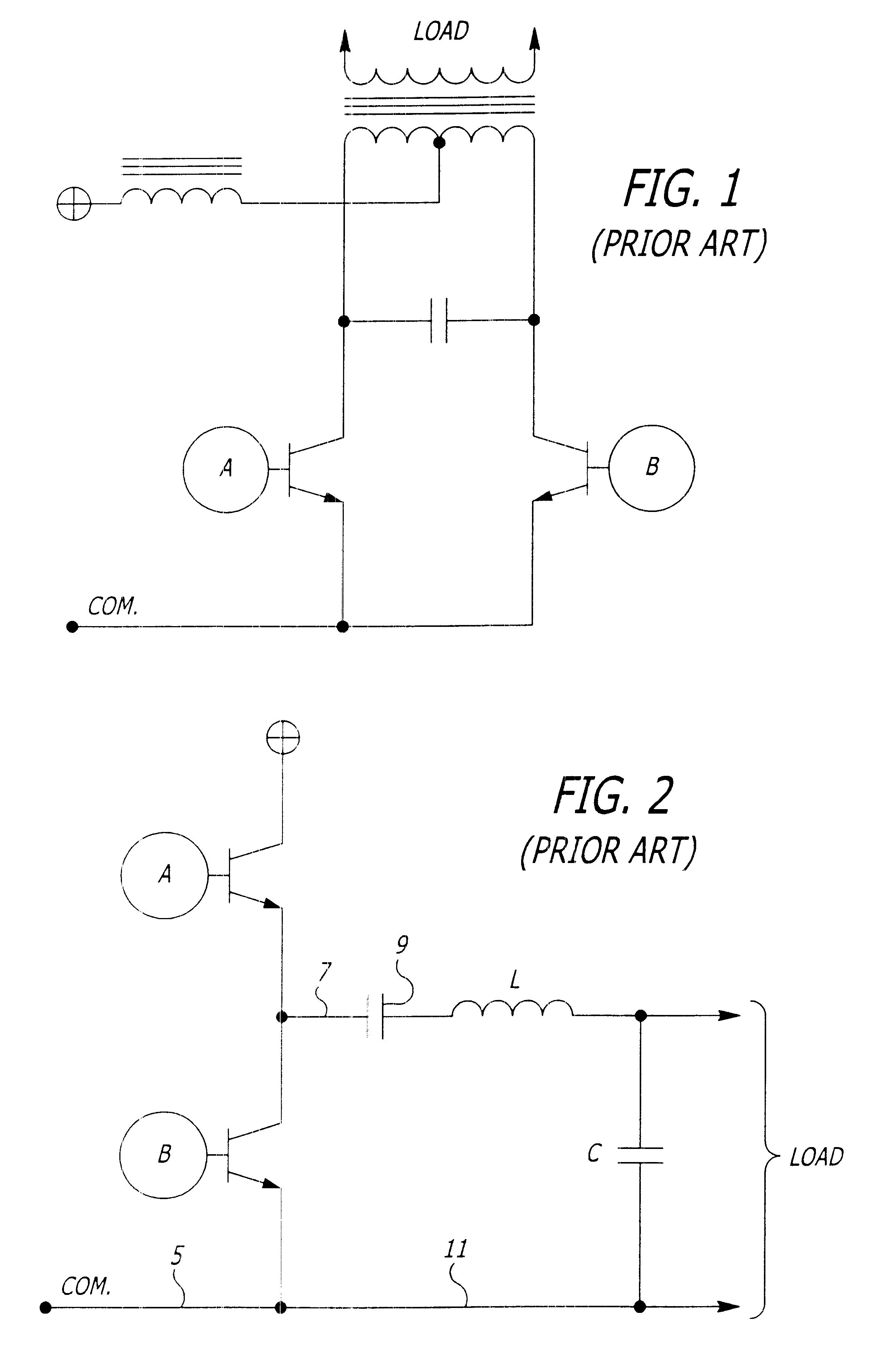
FIG. 1 shows a typical push-pull configuration using NPN transistors with drive input alternately applied at points A and then B. It is obvious that any form of switching device could be used including field effect transistors, vacuum tubes or even mechanical vibrators as used in old fashioned radios.

FIG. 2 shows a half bridge configuration of inverter with switching alternately applied again between points A and B. Because switching device A is not connected to the common bus, only certain types of switches may be used practically in this application. For example, a vacuum tube would be very difficult but not impossible to apply here.

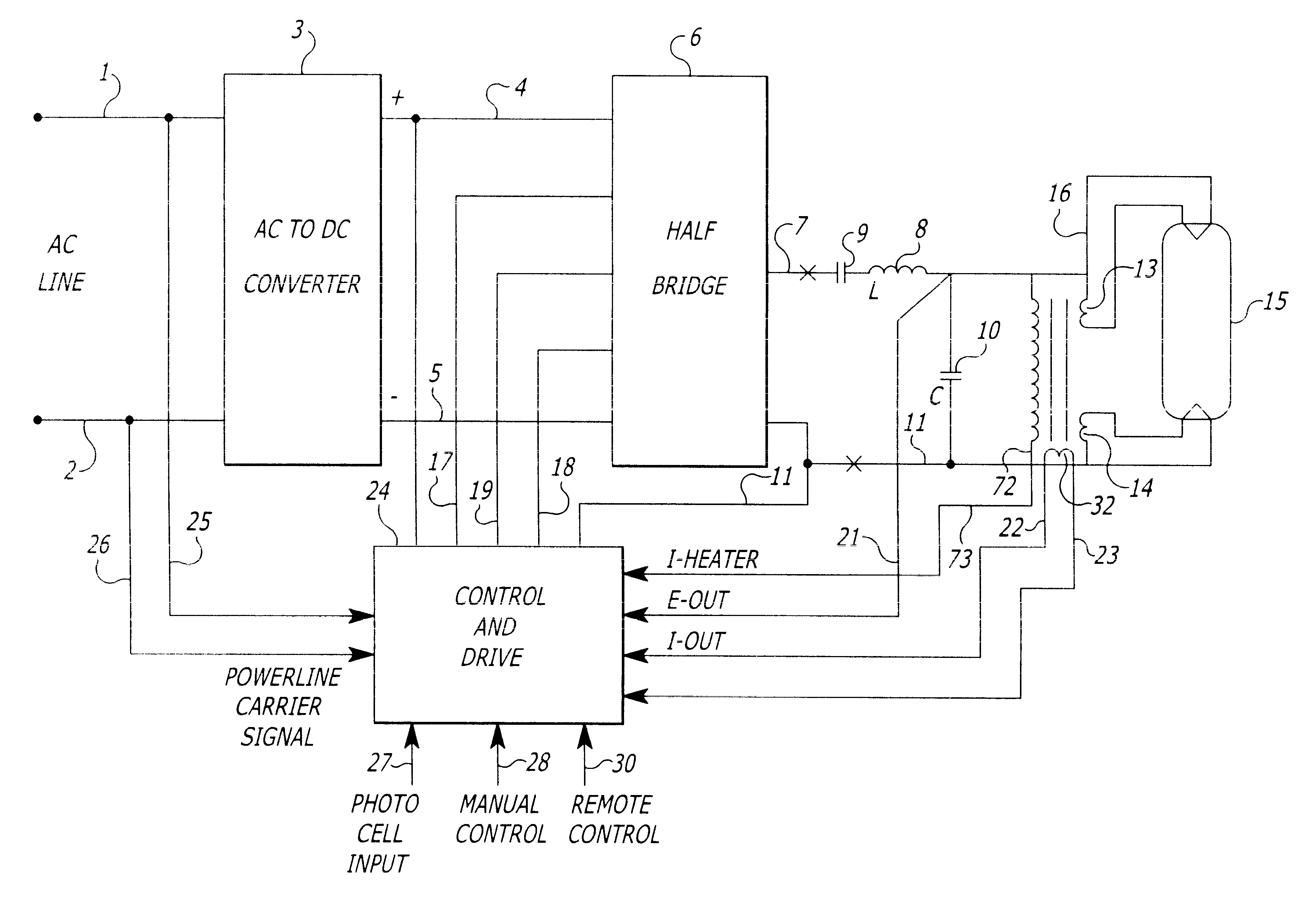
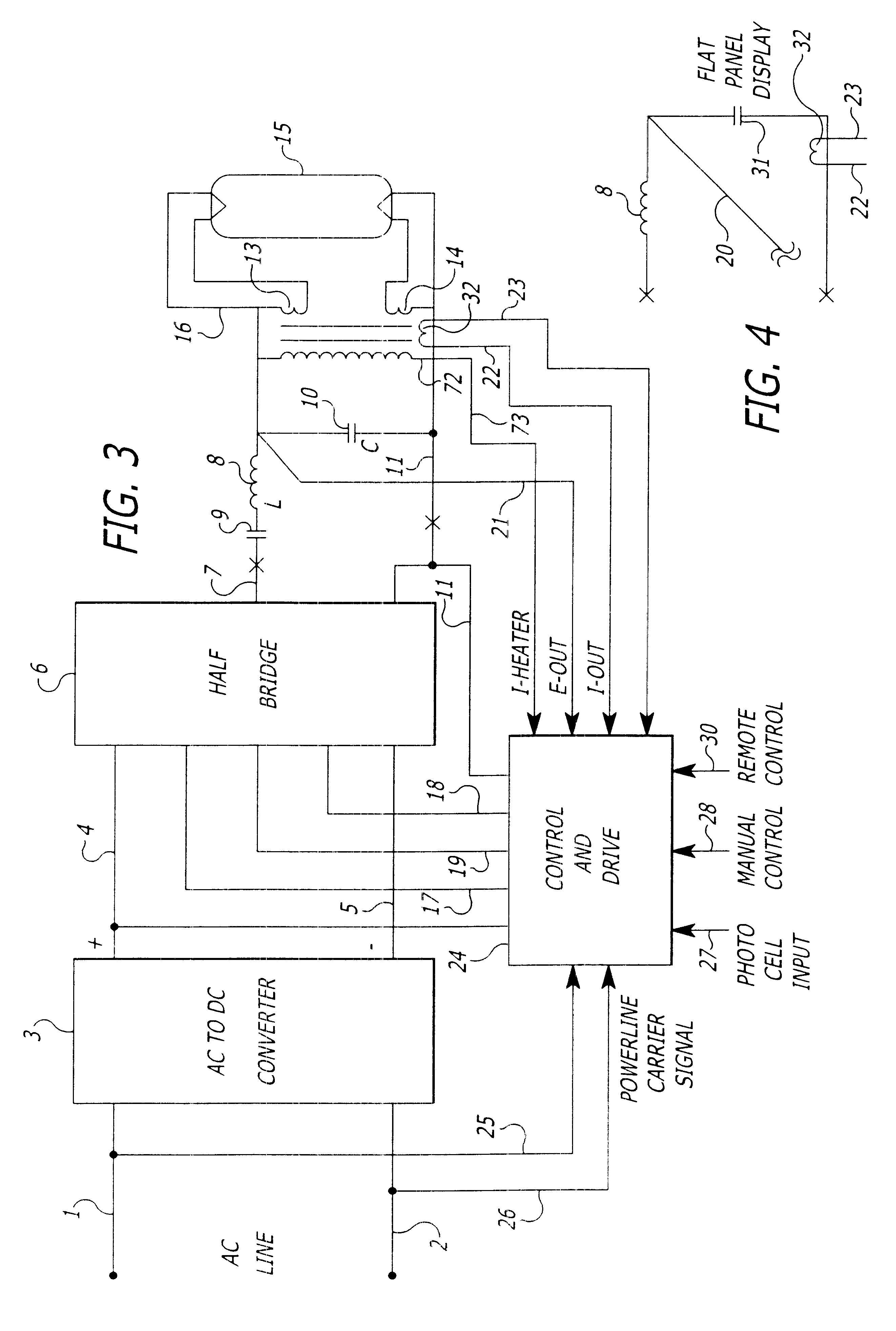
FIG. 3 is a block diagram of a preferred embodiment of the subject invention driving a gas discharge light source.

FIG. 4 depicts a change in the preferred embodiment of FIG. 3 to drive a flat panel display light source.

FIG. 5 is a schematic representation of the drive and control box of FIG. 3.

FIG. 6 is the software flow chart of the most desirable way...


PUM


Abstract

The invention discloses a power inverter using a microprocessor directly drawing the switching transistors and a circuit for computation of the actual power delivered to the load of a switching inverter. In addition, load variation power is achieved by adjusting the frequency or the pulse width of each half cycle and, in the case where a lamp or panel is involved, dimming. Also disclosed is that the microprocessor can be responsive to photometric input to adjust output as well as power line carrier information supplied on the input power to the device.

Description

1. Field of the InventionThe present invention relates to the field of power inverters and to such an inverter for the conversion of an AC or DC supply of power to typically high frequency output power to drive gas discharged lighting sources including fluorescent tubes, HID (high intensity discharge lamps), and UV generating lamps as well as flat panel displays. The system is such that the output power is responsive to a variation in the drive frequency or pulse width. The frequency or pulse width is adjusted by a microprocessor, which in fact, is the oscillator for developing the output frequency.2. Brief Description of the Prior ArtThere are many varied public domain circuits involving the generation of high frequency inputs for driving fluorescent lamps, compact fluorescent lamps, high intensity discharge and other forms of gas discharged lighting. The general terms for such circuits is "switching inverters".There are two basic ways of generating AC output power. The first is a ...

Claims


Application Information

Patent Timeline
Patent Type & Authority Patents(United States)
IPC IPC(8): H02M7/529H02M7/505H05B41/39H05B37/02H05B41/295H05B41/28H05B41/392
CPCH02M7/529H05B37/0263H05B41/295H05B41/3921H05B41/3922Y10S315/04H05B47/185
Inventor STEVENS, CARLILE R.
Owner LUMINOPTICS
Why Eureka
Try Eureka