Method of determining the throughflow of a gas mixture

a gas mixture and throughflow technology, applied in the direction of liquid/fluent solid measurement, volume/mass flow by thermal effects, instruments, etc., can solve the problems of inability to adjust the measurement signal accordingly, the resistance value would rise steeply, and the behaviour is disadvantageous

Inactive Publication Date: 2003-10-07
FAFNIR
View PDF5 Cites 19 Cited by
  • Summary
  • Abstract
  • Description
  • Claims
  • Application Information

AI Technical Summary

Problems solved by technology

A fundamental problem with sensors for measuring the throughflow of a gas is that the measurement signal emitted by the sensor can depend on the composition of the gas, but this composition is often not precisely known, so that the measurement signal cannot be corrected accordingly.
When the method is used for regulation purposes, this behaviour is disadvantageous, in particular if the process to be regulated is itself of only a relatively short duration.
If the temperature of the heating resistor were to increase because of an error in the control or regulation of the heating power supplied to the heating resistor, the resulting resistance value would rise stee...

Method used


Image

  • Method of determining the throughflow of a gas mixture
  • Method of determining the throughflow of a gas mixture
  • Method of determining the throughflow of a gas mixture

Examples


Embodiment Construction

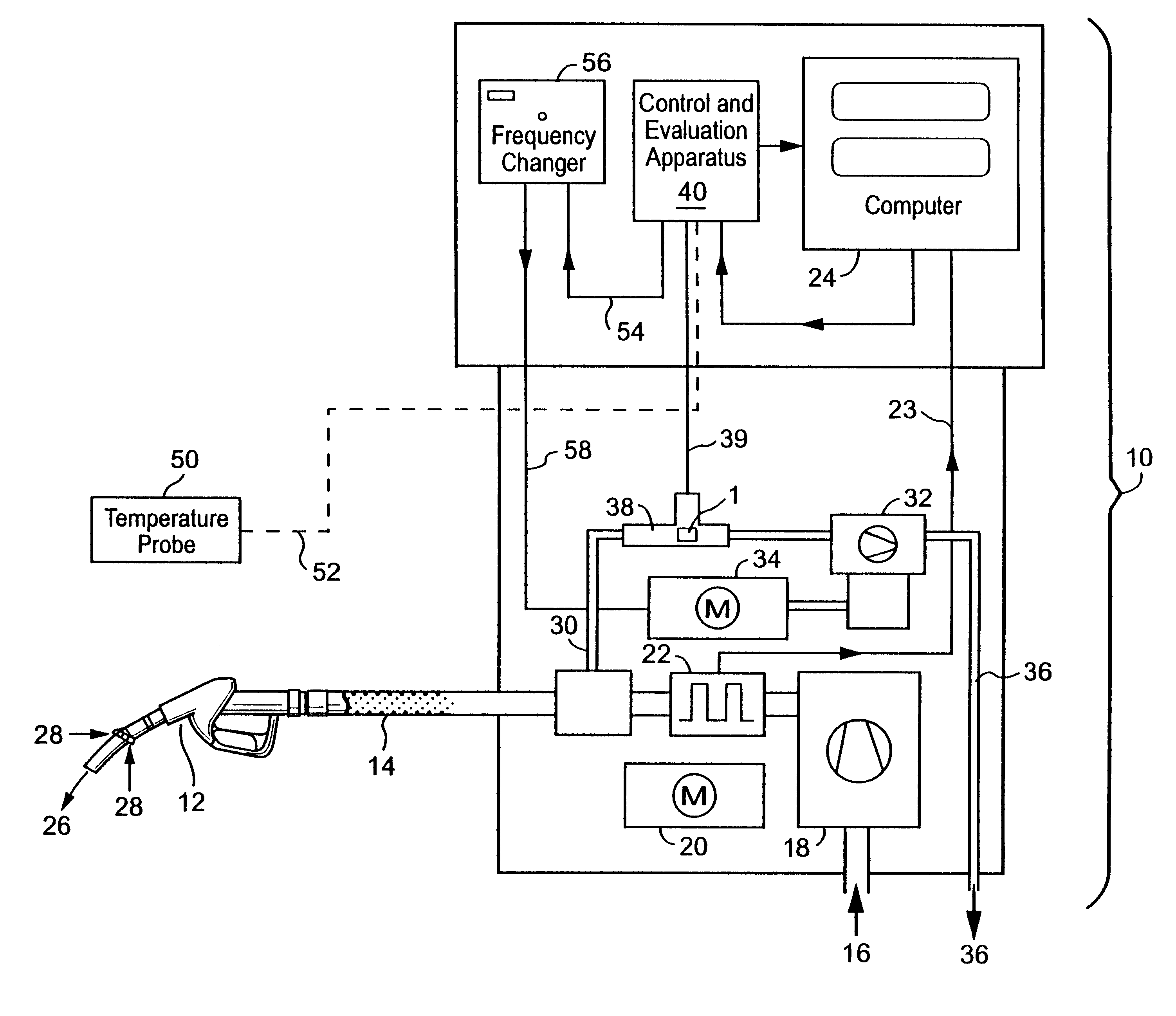
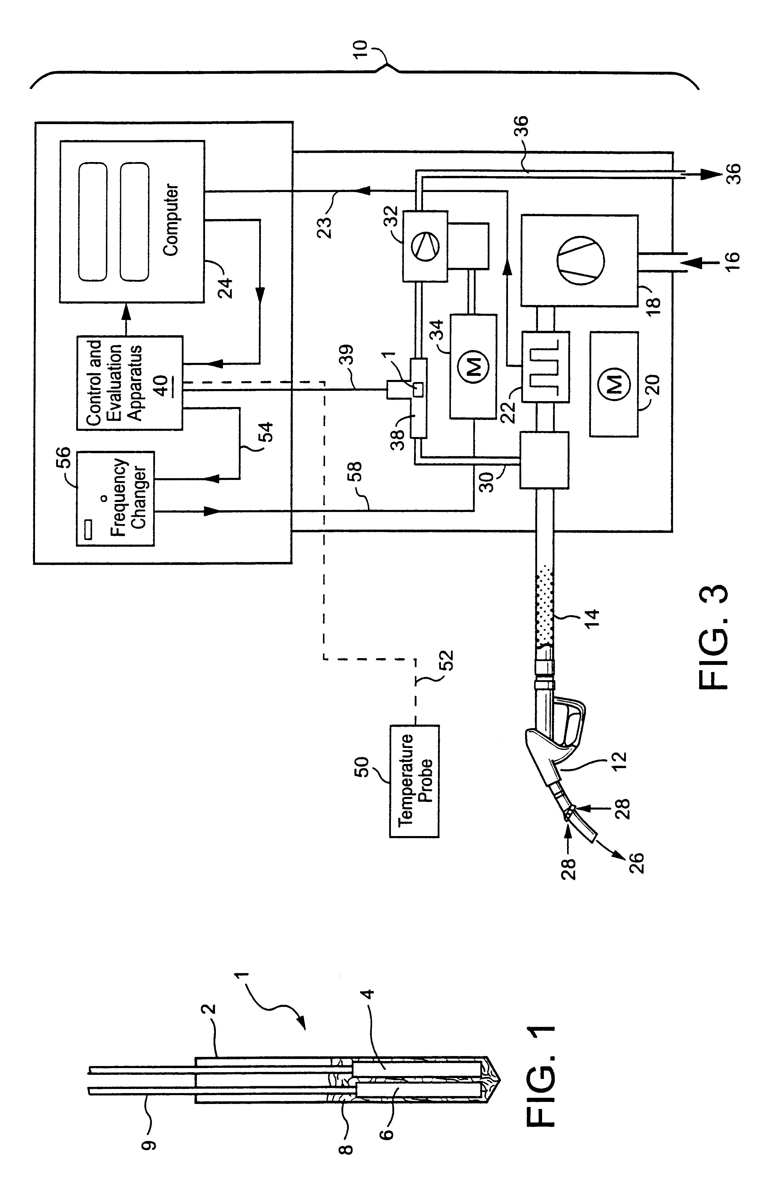
In FIG. 1 there is represented in longitudinal section a version of a flow sensor 1 which can be used to measure the throughflow of a gas mixture. The flow sensor 1 has a cover 2 which encloses a heating device 4 and a temperature probe 6. The cover 2, the heating device 4 and the temperature probe 6 remain in thermal contact via a filling compound 8. Supply lines 9 extend from the heating device 4 and the temperature probe 6.

A PTC resistor serves as heating device in the embodiment. The temperature probe 6 is designed as a platinum precision resistor (Pt 1000) The cover 2 projects into the inside of a pipe, through which the gas, the throughflow of which is to be measured, flows. The amount of heat removed by the flowing gas per unit of time from the flow sensor 1 must then be delivered from the heating device 4 in the stationary state. The power at which the heating device 4 is operated when the temperature recorded by the temperature probe 6 is constant (and e.g. lies above the a...


PUM


Abstract

In a method of measuring the throughflow of a gas mixture, the gas mixture flows past a flow sensor which includes a heating device and a first temperature probe reacting to the temperature of the heating device. A temperature, which is characteristic of the temperature of a liquid above which the gas mixture stands as vapor, is measured with a second temperature probe. A first measurement signal characterizing the composition of the gas mixture and thus its heat dissipation capacity is produced using the known vapor-pressure curve of the liquid and the temperature of the liquid. A second measurement signal characterizing the throughflow of the gas mixture is produced using the heating power supplied to the heating device, the temperature of the first temperature probe and the first measurement signal. The method can be used when monitoring the gas return to a filling system and when controlling the gas pump used therein.

Description

1. Field of the InventionThe invention relates to a method of determining the throughflow (flow rate) of a gas mixture as well as uses of this method, in particular at a petrol station.2. Description of Related ArtWhen filling up a motor vehicle at a petrol station, fuel is poured into the motor vehicle's tank from a petrol pump with the help of a discharge valve. At the same time, the gas mixture which is above the liquid level of the fuel in the motor vehicle's tank and consists of a fuel vapour / air mixture is sucked out via a separate line and conducted into the storage tank of the petrol station. The gas pump used for this should be controlled such that the volume of fuel vapour / air mixture sucked out per time unit is equal to the volume of fuel poured into the tank of the motor vehicle per time unit.A method is known from WO 98 / 31628 for controlling the gas pump in relation to the delivery rate of the fuel pump used to supply the fuel. The throughflow of the sucked-out fuel vap...

Claims


Application Information

Patent Timeline
IPC IPC(8): B67D5/01B67D5/04G01F1/688G01F1/684B67D7/04
CPCG01F1/688B67D7/0486
Inventor SCHRITTENLACHER, WOLFGANGKUNTER, STEFAN
Owner FAFNIR
Why Eureka
Try Eureka