Carpet cleaning machine

Inactive Publication Date: 2003-10-28
WANG KEVIN
View PDF6 Cites 73 Cited by
  • Summary
  • Abstract
  • Description
  • Claims
  • Application Information

AI Technical Summary

Benefits of technology

Methods and apparatus are provided in which a microprocessor controls var

Problems solved by technology

First, an operator may keep his equipment in a poor state of maintenance.
For example, the holding tanks may not be emptied regularly, or the equipment may not be serviced regularly.
Second, operators tend to push their equipment to the limit, for example by setting the thermostat on the heater at an unsafe level.
Third, operators do not necessarily know how to operate the equipment properly.
This problem can be addressed to some extent with operator manuals, but such manuals are of little use where the manuals are not available at an operating site, or an operator is unwilling to wade through a manual to find the relevant section.
Fourth, operators do not necessarily keep accurate records of operating conditions, so that when an equipment failure occurs it is often almost impossible to pinpoint the cause as being something which is or is not covered by warranty.
Fifth, when equipment failures do occur, the equipment may be at a great distance from a suitable repair facility, and individual operators may not have the skills to effectiv

Method used


Image

  • Carpet cleaning machine
  • Carpet cleaning machine
  • Carpet cleaning machine

Examples


Embodiment Construction

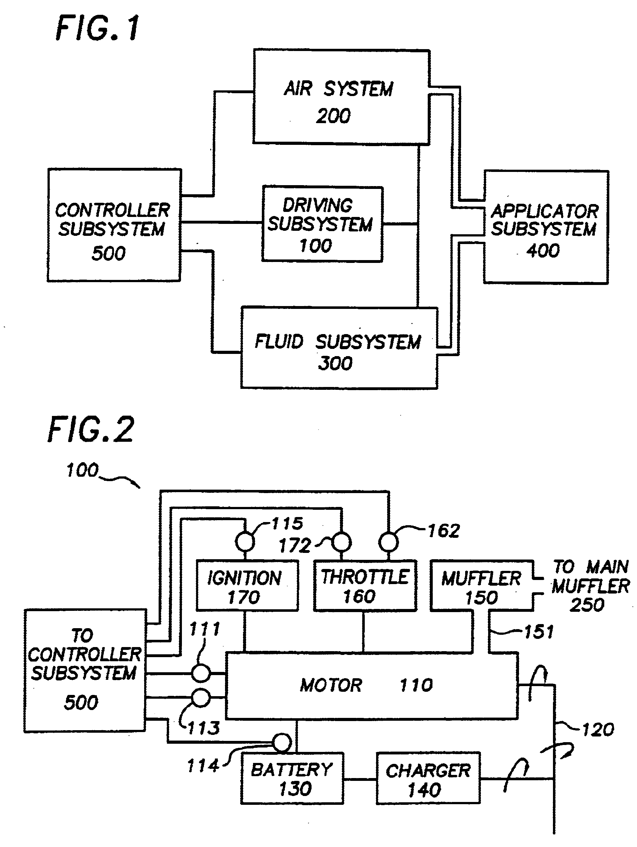
FIG. 1 generally depicts a carpet cleaning machine 1 comprising a power subsystem 100, an air subsystem 200, a fluid subsystem 300, an applicator subsystem 400 and a controller subsystem 500.

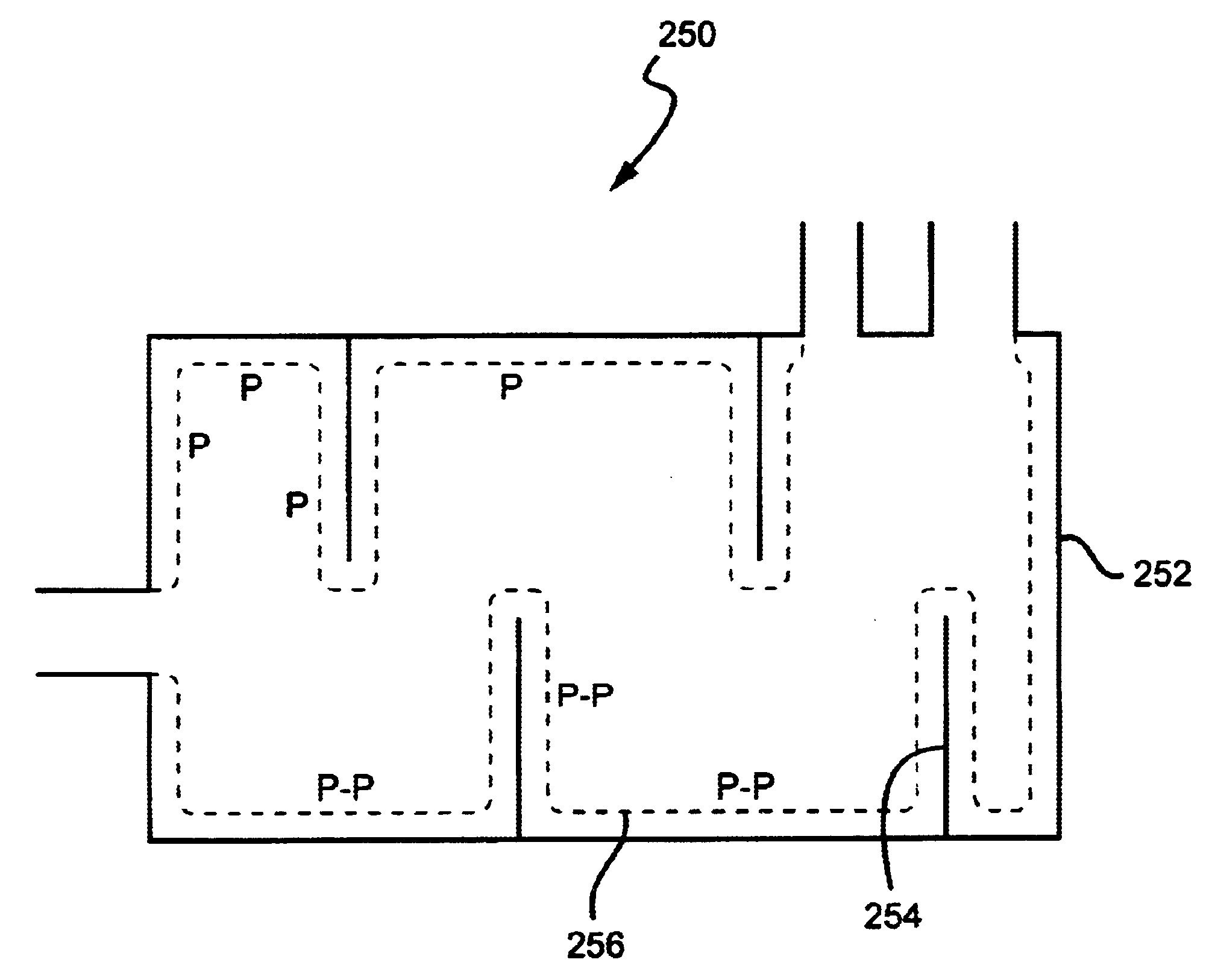
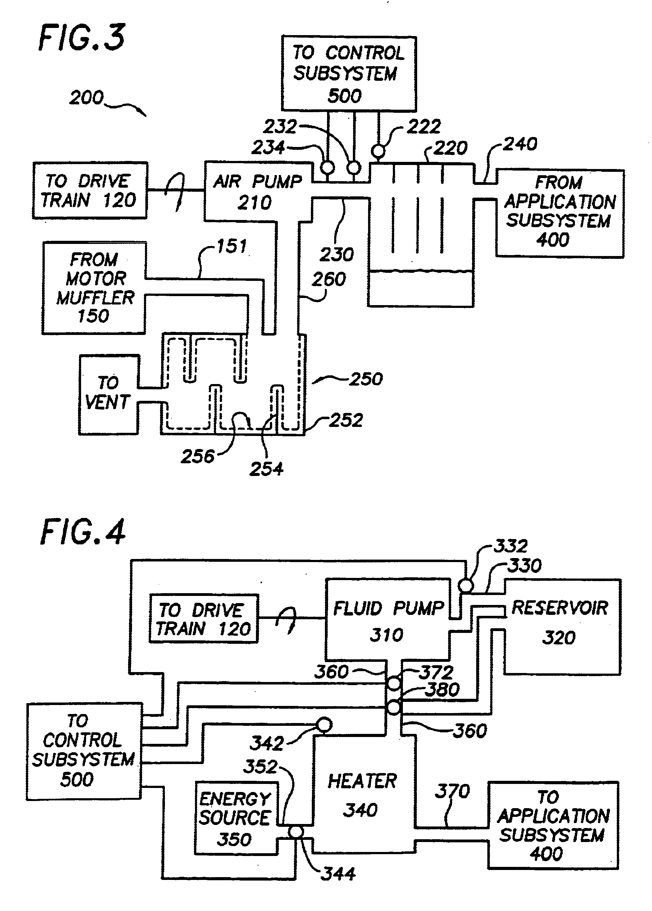
Turning to each subsystem in greater detail, FIG. 2 depicts additional details of the driving subsystem 100, which comprises a motor 110, a drive train 120 a battery 130, a charging circuit 140, a motor muffler 150, a throttle 160 and an ignition 170.

The motor 110 is preferably an overhead cam Kohler.TM. gasoline engine, although engines from other manufacturers may function as well, and other types of engines such as propane, diesel or electric would also work. It is contemplated that the motor 110 would range from about 16 hp to about 50 hp, with a preferred rating of about 25 hp. The motor speed is also not critical, as long as the motor 110 can be geared to provide a rotational speed to the air pump of at least about 900 rpm. A preferred speed of the motor is 3600 rpm.

The preferred driving s...


PUM


Abstract

A muffler for a steam cleaning apparatus comprising a housing having a first and a second inlet, and an outlet, a plurality of baffles disposed within, and coupled to the housing, wherein the plurality of baffles are covered with a foam; wherein the first inlet is pneumatically coupled to an air pump of the steam cleaning apparatus, and wherein the first inlet provides to the housing a stream of humid air from an application subsystem of the steam cleaning apparatus; and wherein the second inlet receives combustion exhaust from a combustion motor that drives an air pump that is operationally coupled to the application subsystem, and wherein the outlet releases air comprising combustion exhaust of the motor.

Description

I. FIELD OF THE INVENTIONThe inventive subject matter herein relates generally to machine cleaning which can be adapted to carpets, drapery, blinds, upholstery and the like.II. BACKGROUND OF THE INVENTIONCarpets, draperies, blinds, upholstery and the like are often cleaned using steam / hot water systems. Since these units usually operate on similar principles, but at different pressures and with different solvents, they are all generically and interchangeably referred to herein as carpet cleaners, carpet cleaning machines, systems, equipment, units and so on. In general, steam / hot water systems include the same basic components, namely a wand for dispensing and recovering a cleaning fluid, an optional reservoir for holding reserve fluid, a fluid pump for providing pressurized cleaning fluid at the wand, an air pump (sometimes referred to as a vacuum pump) for sucking up spent fluid, and a spent fluid holding tank. Carpet cleaning equipment contemplated herein ranges from relatively s...

Claims


Application Information

Patent Timeline
IPC IPC(8): A47L11/00A47L11/40A47L9/28
CPCA47L9/2805A47L9/2831A47L9/2836A47L9/2842A47L9/2857A47L9/2889A47L9/2894A47L11/40A47L11/4011A47L11/4016A47L11/4058A47L11/4069A47L11/4088A47L9/2821A47L2201/00
Inventor WANG, KEVIN
Owner WANG KEVIN
Why Eureka
Try Eureka