Agitators for wave-making or mixing as for tanks, and pumps and filters

a technology of agitators and pumps, applied in the direction of mixing, transportation and packaging, chemistry apparatuses and processes, etc., can solve the problems of increasing operating costs, reducing system performance, and most of the energy loss in a steady stream

Inactive Publication Date: 2003-12-02
SEAMAN ANTHONY E
View PDF60 Cites 57 Cited by
  • Summary
  • Abstract
  • Description
  • Claims
  • Application Information

AI Technical Summary

Benefits of technology

It is an alternate object of the invention to provide such agitators or circulators for salt water aquariums where it is desirable to slosh the water around real thoroughly, which allows reef organisms like filter-feeding coral to get plenty of chance at catching and feeding on plankton that drifts at the whim of the currents set up in the tank.
The pulsing devices in accordance with the invention create turbulence by turning flow ON and OFF or alternating the flow from high to low and distributing it over the desired volume. When the pulsing wave-maker / mixer or pump is pulsed ON, it allows fluid to flow over a volume for a set period of time. During this time, the flow is a steady stream with most of the turbulence at the boundaries of the stream. When the device is pulsed OFF, the energy from the fluid stream is dissipated into the stationary fluid. This creates turbulence across the entire volume and not just at the boundaries of the flow. Low frequency pulsing gives the fluid more time to dissipate its energy, whereas higher frequency pulsing gives the fluid less time.
The sweeping devices in accordance with the invention create turbulence by sweeping the flow over a large volume. As the devices sweep or oscillate, the flow is turned ON and OFF at any fixed location along the flow path. This creates a pulsing effect over any fixed volume that is encompassed by the fluid path from the sweeping or oscillating discharge. As the fluid stream enters and exits the fixed volume, the energy from the fluid is dissipated into the stationary fluid. This creates turbulence across the entire volume and not just at the boundaries of the flow. Low frequency rotating or oscillating gives the fluid more time to dissipate its energy: higher frequency rotating or oscillating gives the fluid less time.
The devices that (i) both sweep and pulse (ii) pumps or pump heads that pulse ON and OFF (with or without built in wave-makers / mixers), (iii) pumps or pump heads with automatic valves that switch flow between two or more exit ports or wave-makers / mixers, (iv) or any of the moving or stationary devices outlined above that work in fluids or a slurry, operate on a combination of previously outlined principles. In aquariums, where a high pressure, steady stream flow can affect the livestock (e.g., fish), the pulsing, sweeping, oscillating, or moving wave-makers / mixers allow for the use of a high pressure pump. The pulsing, sweeping, oscillating or moving breaks up a high pressure stream so it can still reach a greater distance into the aquarium from the discharge but not injure the livestock. The turbulence helps create a more natural marine ecosystem. The moving systems have the added benefit of ensuring water movement over an exact volume of the tank. These devices also ensure rapid, thorough and cost effective mixing of chemicals, foods, and so on.
Any of the sweeping or pulsing devices, or any combination of devices mentioned above when placed inside a filter, filter canister or filter box, work by creating turbulence in, and a washing down of the filtering media from inside. The result is the suspension of particles in a slurry inside the filter or a washing of the particles to a holding area which keeps them from clogging up the pores of the filter media. The particles still cannot pass the filter media, but their suspension inside or placement away from the filter will keep the pores open and allow for greater flow and pressure. This, in turn will increase system performance, reduce filter changes and save energy.
The devices that depend on movement, including velocity and positioning, of rotating impellers, beaters, chopping blades, whisks, and so on in a tank, bowl, container and so on, work by moving the rotating impeller to various positions in the tank to ensure thorough mixing, chopping, blending, and so on, of the solids or the slurry. By moving the impeller and motor on a track in a programmable routine, significant improvements are made to the process. The motor can be optimized for power use, for the diameter of the impeller and for the intended use. Various container sizes can be used. The mixing will be thorough. And the process will require minimal operator attention. In short, the process will be efficient, less time consuming and cost effective.

Problems solved by technology

Most of the energy losses in a steady stream occur at the boundaries of the flow.
The dissipation of energy in large volumes of fluid, whether from a wave or a stream, causes turbulence.
This, in turn, causes a decrease in system performance and an increase in operating costs.
The main drawback to these pumps is the weak coupling between the magnets.
The magnetic coupling cannot transfer motor torque to the impeller efficiently.
Small changes in motor speed, from minor voltage fluctuations, causes significant changes in the pump output.
While this type of pump recirculates water and low viscosity fluids without any problem, it has little value for high viscosity fluids.
For the work they perform, magnetic drive pumps consume more power than direct drive pumps.
As mentioned above, the dissipation of energy stored in the fluid stream causes turbulence in the tank.
This creates turbulence across the entire volume and not just at the boundaries of the flow.
This results in an additional pulsing effect in the tank.
While this has its advantages for wave-making / mixing there are practical limits to how high the extension can get.
The extension reduces flow to the rotating exit port (friction), increases wear on the bearing and requires more torque from the turbine or motor.

Method used


Image

  • Agitators for wave-making or mixing as for tanks, and pumps and filters
  • Agitators for wave-making or mixing as for tanks, and pumps and filters
  • Agitators for wave-making or mixing as for tanks, and pumps and filters

Examples


Embodiment Construction

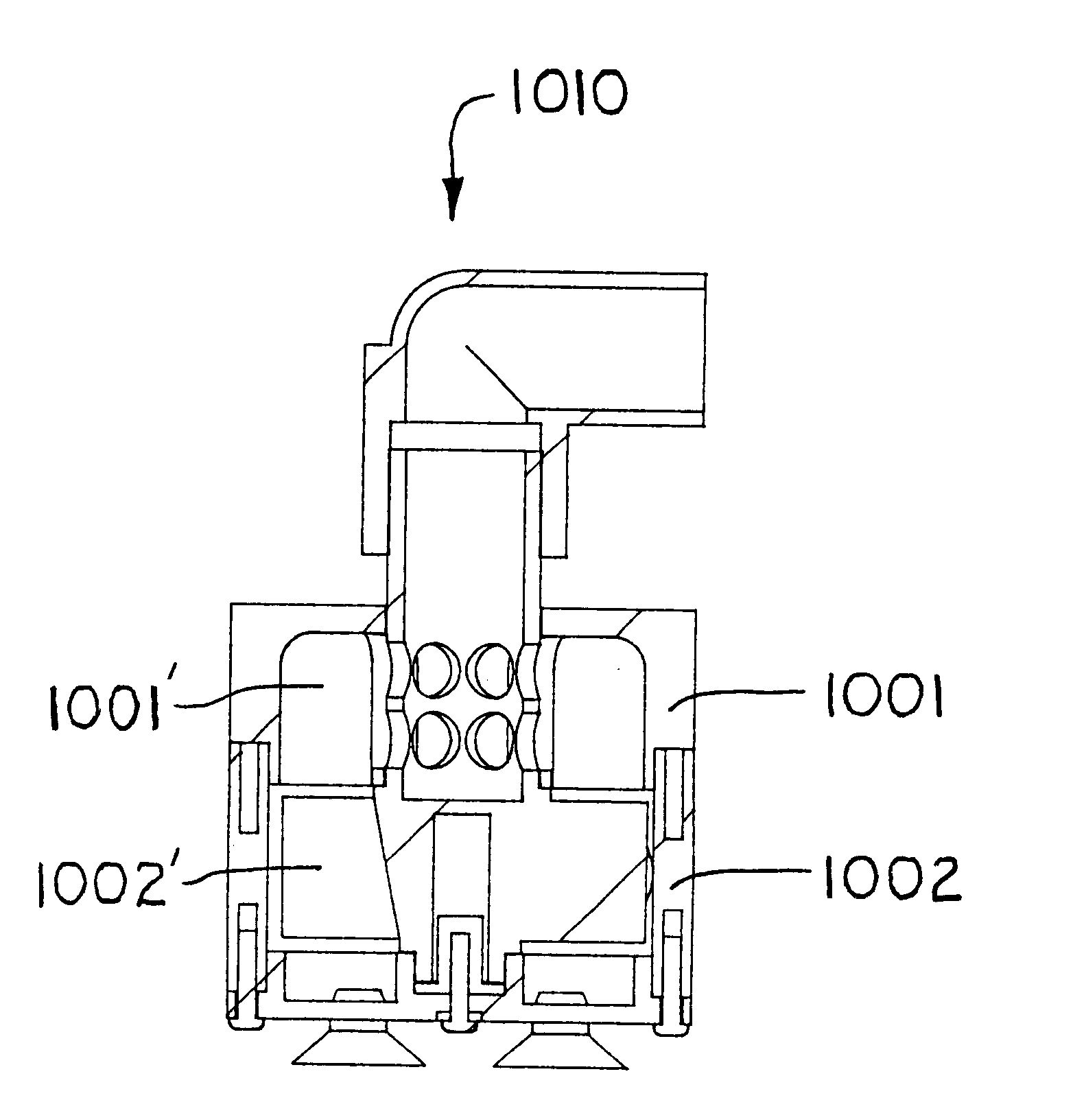
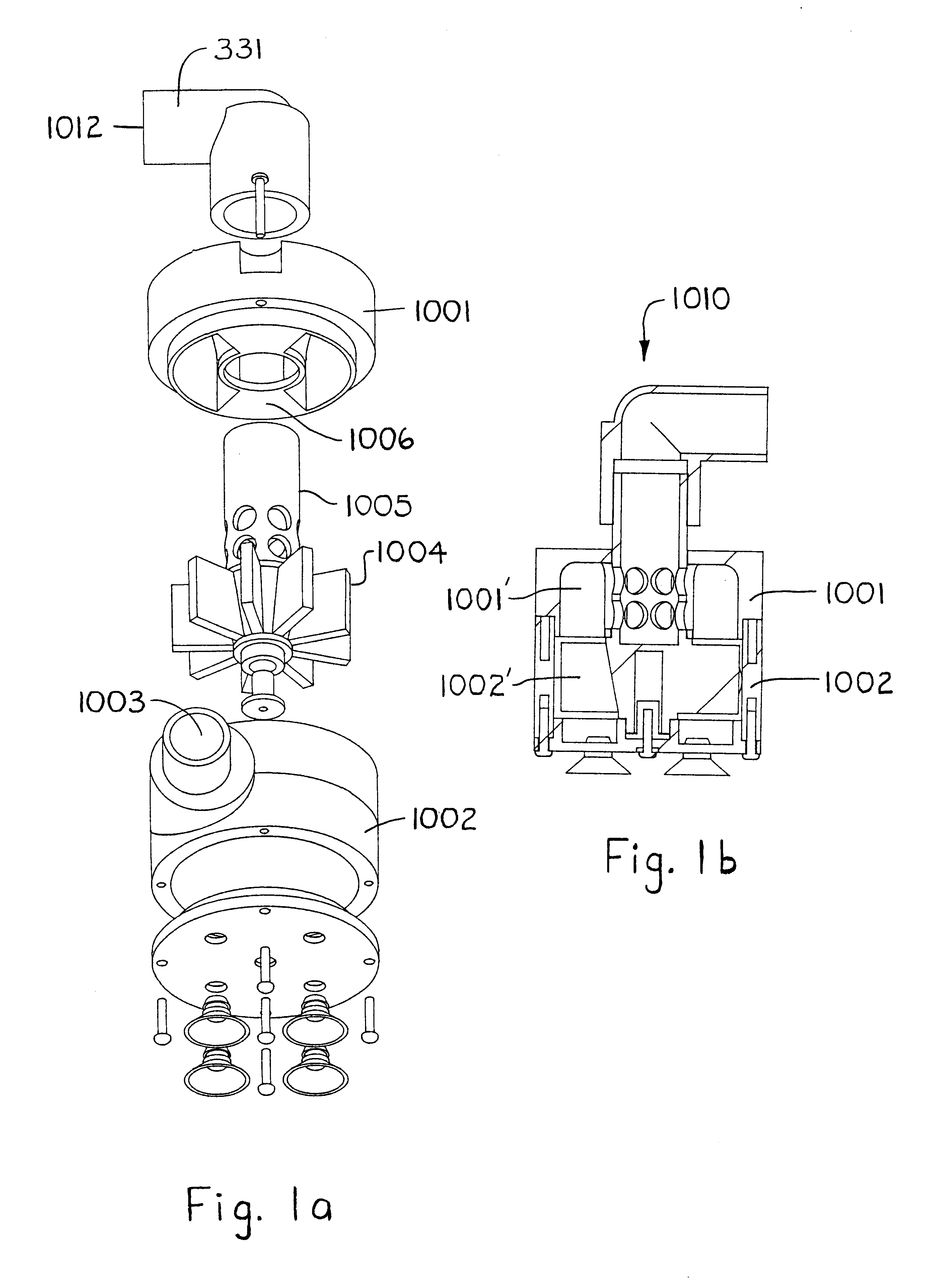
FIG. 1a and 1b show a rotator 1010 in accordance with the invention. The rotator 1010 includes upper and lower housings 1001 and 1002 which respectively define upper and lower plenums 1001' and 1002'. The lower housing encloses the turbine 1004, which is driven at constant speed by the steady infeed flow entering through the inlet 1003. The turbine 1004 has appended to it a hollow apertured shaft 1005 which extends through the partition wall 1006 between the upper and lower plenums, to couple to a 90.degree.-nozzle forming the discharge port 1012 for this rotator 1010. The 90.degree. discharge port 1012 protrudes out above a top wall of the upper housing 1001. The flowthrough of the infeed stream in the inlet 1003 causes the turbine 1004 to spin. The spinning turbine 1004 spins the directly coupled 90.degree. discharge port 1012 through complete rotations. The infeed stream flows up out of the vanes of the turbine 1004, into the upper plenum 1001',into the lumen of the hollow shaft ...


PUM


Abstract

A tank agitator connects to a low head feed and causes agitation by discharging through a port that might rotate, oscillate, or otherwise issue a pulsing stream. This agitator has a housing with a turbine plenum and an exhaust plenum. A turbine in the turbine plenum spins by the flowthrough of the feedwater and exhausts to the exhaust plenum. A hollow drive shaft is spun by the turbine and extends through the exhaust plenum and to terminate outside the housing. It has an aperture that allows water in the exhaust plenum to flow into its lumen. A nozzle caps the shaft and is bent such that the discharge issuing therefrom sweeps in circles with the spinning of the drive shaft. A variant form of the agitator includes a drive train that incorporates a drag link to convert the spinning input of the turbine into an oscillating output in the drive shaft. In another variant form, the discharge is pulsed. To do this, the exhaust plenum lies between an opening to the turbine plenum and a port in the housing wall to the outside. A blocker door is coupled to and driven by the spinning turbine to cycle between uncovering and covering one of the exhaust opening and the discharge port. Given the foregoing, the discharge stream issuing from the discharge port will pulse between alternating phases of flow and quiescence.

Description

1. Field of the InventionThe invention relates to agitators or circulators for inducing currents--or waves if that is preferred--in a given tank. One example illustrative use environment for the invention involves salt water aquariums in which it is desirable to generate a wave and / or current environment similar to an actual reef so that filter-feeding organisms like coral are given plenty of plankton circulated by them to feed on. Other example use environments include without limitation process industries like the chemical, food, or water treatment industries and so on, for use in mixing tanks to mix dissolving chemicals or blend fluids or the like, including suspending or dispersing particles, bubbles, droplets, fluid clumps and so on.Additional aspects and objects of the invention will be apparent in connection with the discussion further below of preferred embodiments and examples.2. Prior ArtWaves at the surface of fluids appear as a variation of the familiar sine curve in mat...

Claims


Application Information

Patent Timeline
Patent Type & Authority Patents(United States)
IPC IPC(8): B01F5/02B01F5/00B01F5/10
CPCB01F5/0218B01F5/0225B01F5/0243B01F5/0231Y10S239/01B01F5/10A01K63/047B01F25/212B01F25/2121B01F25/2122B01F25/2124B01F25/50
Inventor SEAMAN, ANTHONY E.
Owner SEAMAN ANTHONY E
Why Eureka
Try Eureka