Measuring jitter of high-speed data channels

a high-speed data channel and data jitter technology, applied in the direction of pulse characteristics measurement, transmission monitoring, baseband system details, etc., can solve the problems of data recovery errors affecting the integrity of the overall network, clock recovery circuits sensitive to input jitter (time distortion) and level distortion, and the inability to distinguish between amplitude and phase modulation components

Inactive Publication Date: 2003-12-09
CREDENCE SYSTEMS
View PDF2 Cites 112 Cited by
  • Summary
  • Abstract
  • Description
  • Claims
  • Application Information

AI Technical Summary

Problems solved by technology

These clock recovery circuits are sensitive to input jitter (time distortion) and level distortion.
Excessive jitter could cause errors in the data recovery impacting the bit error rate (BER) and the integrity of the overall network.
Jitter sources could come from power supply noise, thermal noise from the PLL components and limited bandwidth of the transmitter (affecting mostly the Data Dependent Jitter-DDJ).
With a spectrum analyzer one can measure the power of the signal as a function of frequency with wide dynamic range, ho...

Method used


Image

  • Measuring jitter of high-speed data channels
  • Measuring jitter of high-speed data channels
  • Measuring jitter of high-speed data channels

Examples


Embodiment Construction

correlation exercise was performed on a 1 Gbps data source, while sourcing a 500 MHz clock (101010..). FIG. 6 shows the 1-Gpbs data source. The oscilloscope (HP54120B) was set to acquire 1000 samples in a 3% voltage compare window out of the full signal swing (800 mV) with self-trigger. The undersampler used was set to a 1 ps effective sampling resolution, and acquired 75 samples across each of the two signal transition edges. The results were correlated with a start / stop time interval measurement instrument (DTS2070) and the oscilloscope histogram measurement. The results of this correlation are given in Table 1. The peak-to-peak jitter of the undersampled comparator measurement is lower than that of the other methods due to the smaller number of samples taken.

TABLE 2

Apparatus

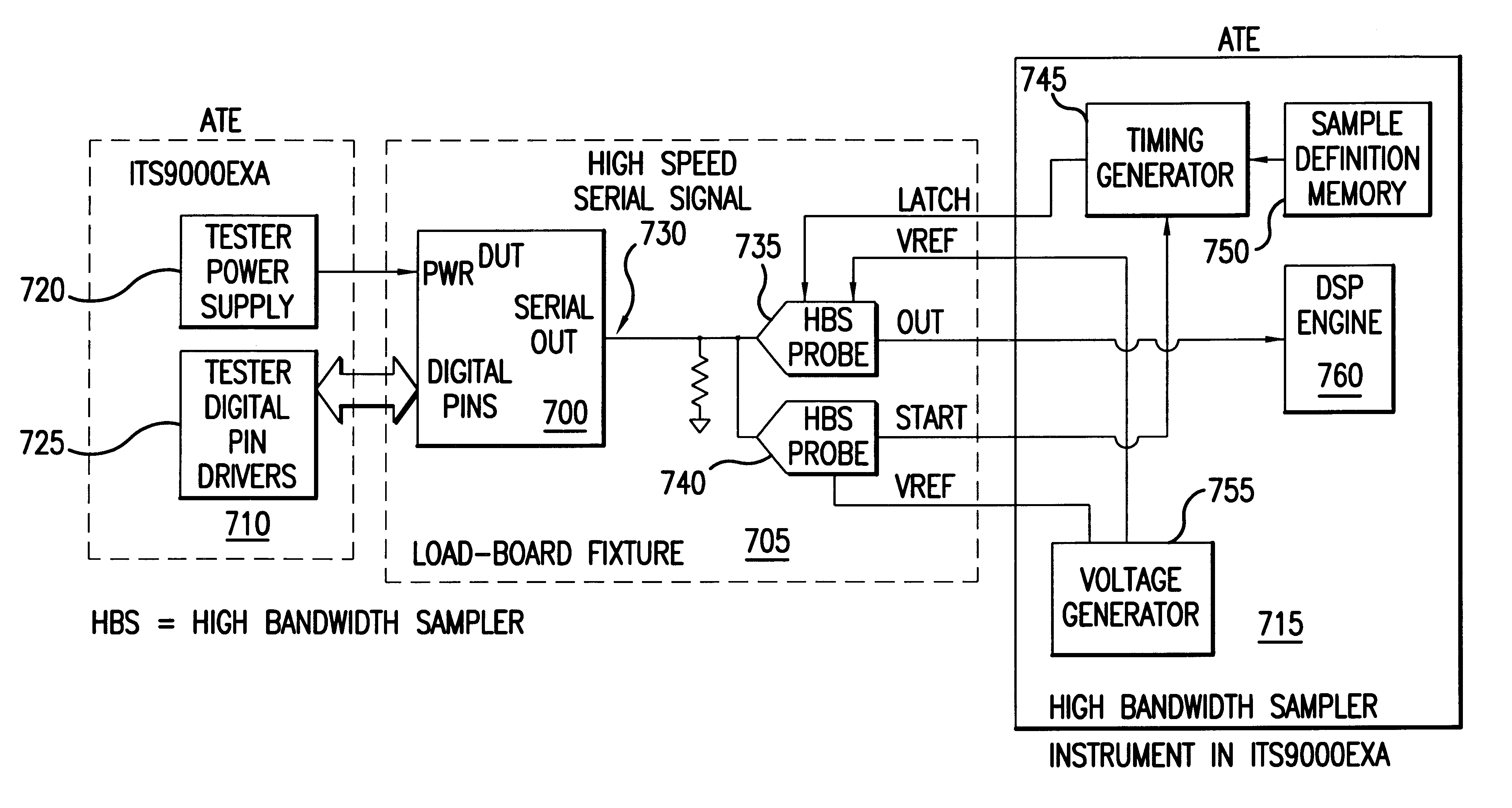
FIG. 7 shows one possible arrangement suitable for performing methods in accordance with the invention. Referring to FIG. 7, a device under test (DUT) 700 is inserted in a device loadboard fixture 705. Device ...


PUM


Abstract

A jitter measurement technique utilizing a high-bandwidth undersampling voltage measurement instrument is presented. A trigger is derived from the a signal having a repetitive signal pattern. The signal is compared with a threshold at a plurality of times relative to the trigger during multiple repetitions of the signal pattern to produce measurement samples indicative of signal level relative to the threshold. The measurement samples are used to determine the probability of signal edge states as a function of time for the multiple repetitions. The probability of signal edge states are used to determine an edge probability density as a function of time. A histogram of signal state transition times can be prepared from the edge probability density. Mean deviation of edge transitions of the signal can be estimates, and standard deviation of edge transitions of the signal can be estimated to give the root-mean-square (rms) jitter of the signal.

Description

1. Field of the InventionThe invention relates to measurement of high-speed data channels, particularly measurement of jitter in clock signals using self-triggered undersampling techniques.2. The Prior ArtIn serial data communication standards such as Ethernet and ATM (speed range from 100 Mbps to 622 Mbps) or the higher speed new communication standards such as Fibre Channel, Firewire (S800 and S1600) and GigaBit Ethernet, the data and clock are embedded within the signal codes. Because of these characteristics the receiver must have special clock recovery circuitry (implemented with a phase-locked loop (PLL)), that would extract the data and clock from the "analog" symbols received through the media. These clock recovery circuits are sensitive to input jitter (time distortion) and level distortion. To guarantee proper data reception in any network the transmitter must meet a certain budget of transmitted jitter. Typical measurements in ATE systems use a GPIB instrument which can b...

Claims


Application Information

Patent Timeline
IPC IPC(8): H04L1/24G01R29/02H04L25/02
CPCG01R29/02H04L1/24H03M1/1285
Inventor DALAL, WAJIHROSENTHAL, DANIEL A.
Owner CREDENCE SYSTEMS
Why Eureka
Try Eureka