Capillary tube assembly with replaceable capillary tube

a capillary tube and assembly technology, applied in the field of capillary tube assembly with replaceable capillary tube, can solve the problems of low sample throughput and loss of laboratory revenue, and achieve the effect of easy and quick removal

Inactive Publication Date: 2003-12-23
THERMO FINNIGAN
View PDF11 Cites 48 Cited by
  • Summary
  • Abstract
  • Description
  • Claims
  • Application Information

AI Technical Summary

Benefits of technology

It is an object of the present invention to provide a heated capillary assembly in which the cap...

Problems solved by technology

This means a low sample throughput which t...

Method used


Image

  • Capillary tube assembly with replaceable capillary tube
  • Capillary tube assembly with replaceable capillary tube
  • Capillary tube assembly with replaceable capillary tube

Examples


Embodiment Construction

)

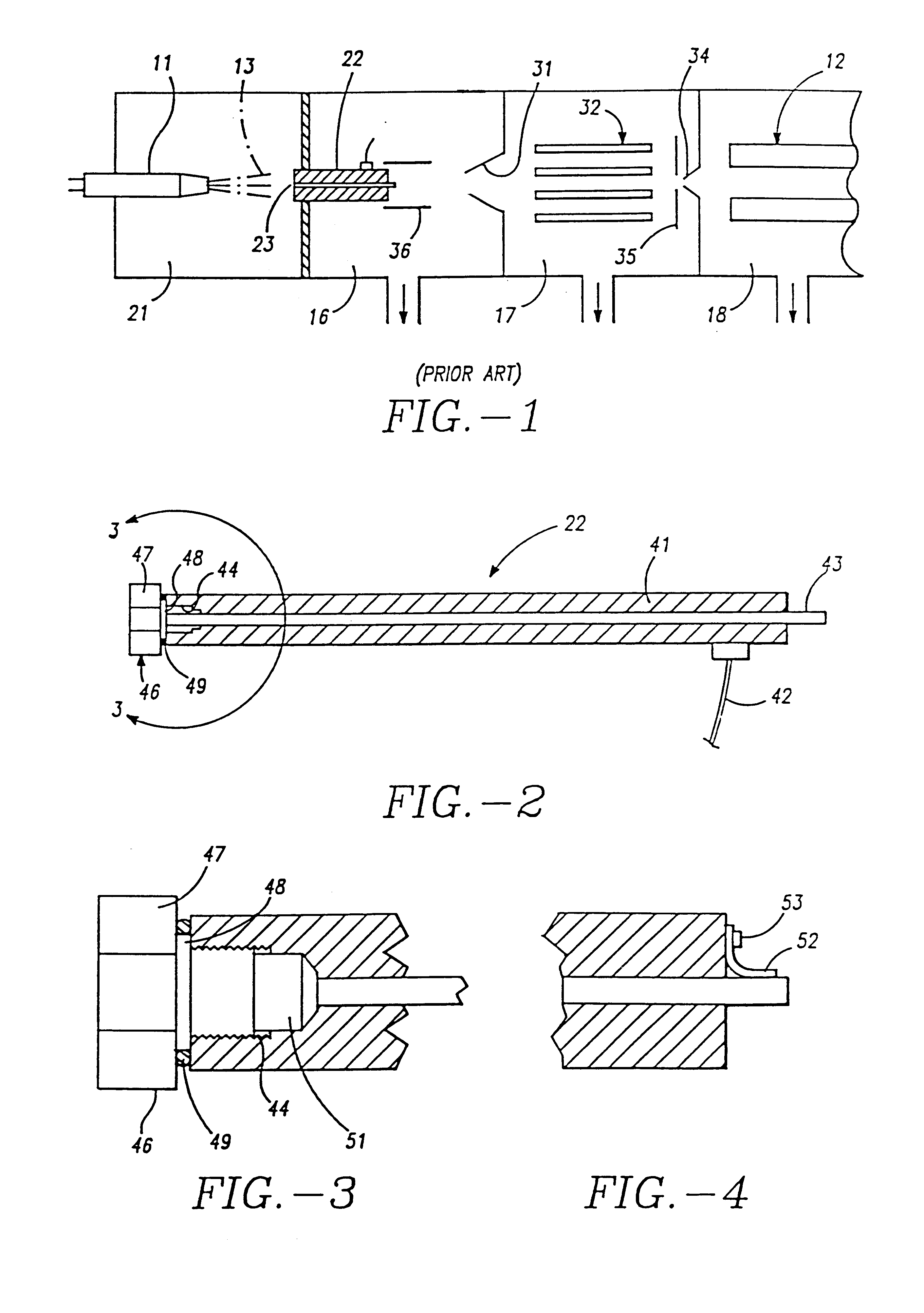
Referring to FIG. 1, a prior art mass spectrometer with an ionization source having probe 11 is illustrated coupled to a mass analyzer 12 by an ion transmission assembly. It is apparent to one skilled in the art that the ion source can be operated at pressures ranging from below atmospheric pressure to above atmospheric pressure. Although a quadrupole mass analyzer 12 is illustrated, it will be apparent to those skilled in the art that the mass analyzer may include, and is not limited to, time of flight (TOF), quadrupole, Fourier transform (FTMS), ion trap, magnetic sector or hybrid mass analyzers. By way of example, the ion source may be an atmospheric pressure ion source (API). More particularly, the ion source may comprise an electrospray ion source (ES) or atmospheric pressure chemical ionization source (APCI). In any event, the source includes an ion probe 11 which forms an ion spray 13. The ionization mechanism involves the desorption at atmospheric pressure of ions from the ...


PUM


Abstract

The present invention relates to a heated capillary assembly which connects an atmospheric pressure ionization source to a lower pressure mass analyzing system which comprises a capillary tube removably secured to, and extending through the bore of a capillary support assembly.

Description

This invention relates generally to a capillary tube assembly which connects an atmospheric pressure ionization chamber to a lower pressure mass analyzer assembly, and more particularly to a capillary assembly having a removable capillary tube.When an atmospheric pressure ionization (API) source such as an electrospray (ES) or atmospheric pressure ionization (APCI) source is installed on a mass spectrometer system, the gas flow from the atmospheric pressure ionization chamber into the vacuum system of the mass spectrometer must be set to match the pumping capacity of the vacuum pumps used. Small diameter orifices and capillary tubes are the two methods most often used to limit the gas flow from the atmospheric pressure spray chamber into the vacuum system of the mass spectrometer. These capillary tubes are often heated to provide thermal energy to the solvated ions passing through them, thus desolvating these ions.Non-volatile material from the samples being analyzed by the mass spe...

Claims


Application Information

Patent Timeline
IPC IPC(8): H01J49/04H01J49/02H01J49/10G01N27/62
CPCH01J49/0404
Inventor ABRAMSON, JEFFREY B.GORE, NIGEL P.KHOSLA, MUKULMYLCHREEST, IAIN C.TANG, KEQIJOHNSON, ERIC B.
Owner THERMO FINNIGAN
Why Eureka
Try Eureka