Upper bundle steam generator cleaning system and method

a cleaning system and steam generator technology, applied in the direction of machines/engines, flush cleaning, lighting and heating apparatus, etc., can solve the problems of affecting the reducing the cleaning efficiency of the generator, so as to reduce the exposure of personnel to radiation, maximize the cleaning effect, and save water energy

Inactive Publication Date: 2004-01-06
FOSTER-MILLER
View PDF101 Cites 28 Cited by
  • Summary
  • Abstract
  • Description
  • Claims
  • Application Information

AI Technical Summary

Benefits of technology

It is a further object of this invention to provide such an upper bundle steam generator cleaning, inspection, and repair system which eliminates the need to use chemical cleaning techniques and overcomes the disadvantages inherent in chemical cleaning or which can be used in conjunction with chemical cleaning.
It is a further object of this invention to provide such an upper bundle steam generator cleaning, inspection, and repair system which adequately cleans the upper bundles of the steam generator using water under pressure even within the close confines of the tubes of the steam generator.
It is a further object of this invention to provide such an upper bundle steam generator cleaning, inspection, and repair system which successfully delivers sufficient water energy to remove scale and also distributes ...

Problems solved by technology

Steam generators were designed to last upwards of forty years but in practice such reliability figures have proven not to be the case.
The problem is that sludge from particulate impurities suspended in the feed-water forms on the tubes which greatly affects the efficiency of the generator and can even cause the tubes to degrade to the point of causing fissures in the tubes.
If radioactive primary fluid within the tubes seeps into the secondary side, the result can be disastrous.
Plugging or otherwise servicing such fissures is time consuming and results in expensive down time during which power must be purchased from other sources at a great expense.
There are known methods for cleaning the tubes proximate the bottom of the steam generator using flexible lances and the like which clean the tubes using water under pressure, but since a typical steam generator can be thirty feet tall, it is difficult to reach the sludge at the upper levels of the tubes using water jets.
First, chemical cleaning is very expensive (from $5,000,000 to $10,000,000 per applicat...

Method used


Image

  • Upper bundle steam generator cleaning system and method
  • Upper bundle steam generator cleaning system and method
  • Upper bundle steam generator cleaning system and method

Examples


mast embodiments

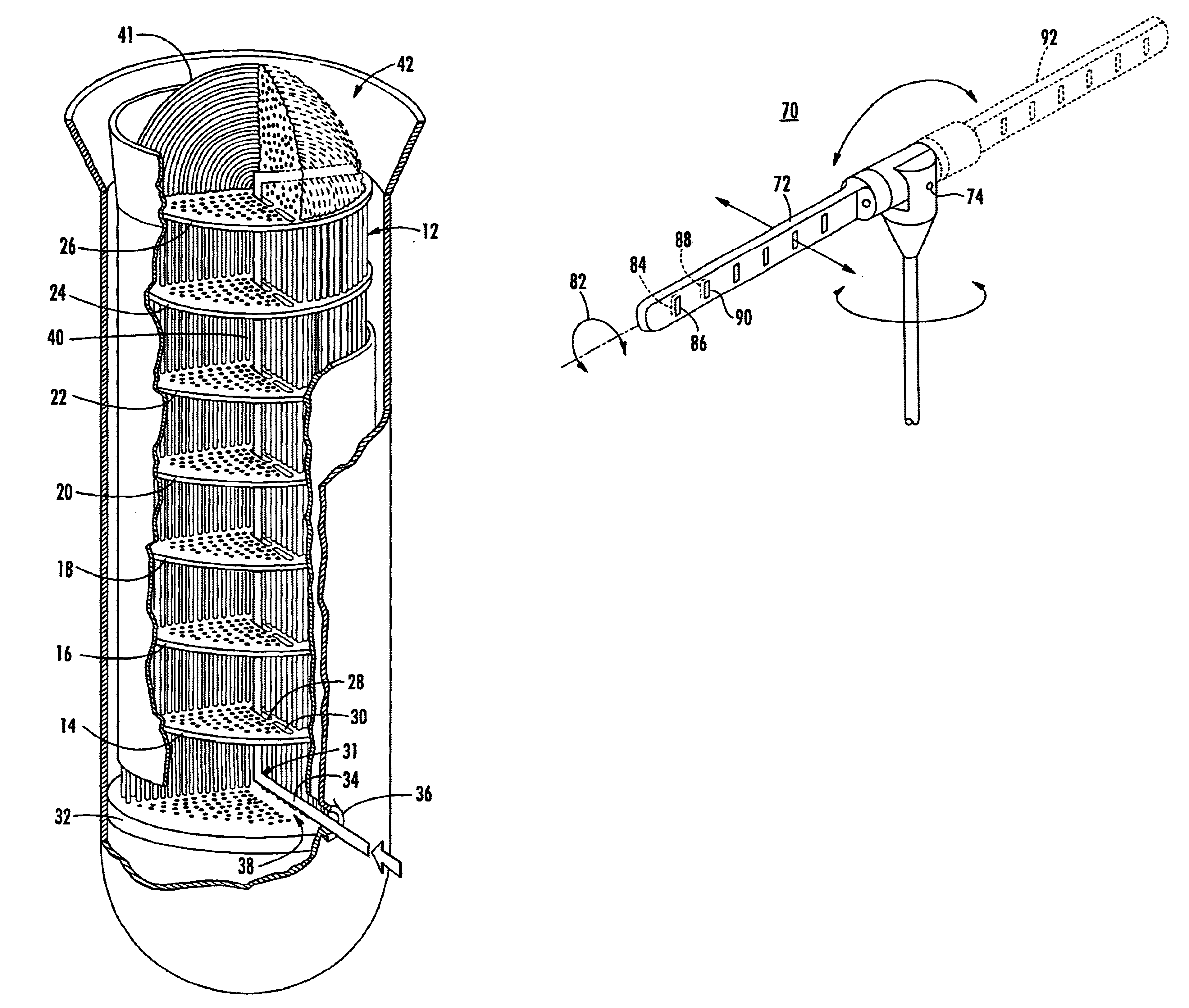
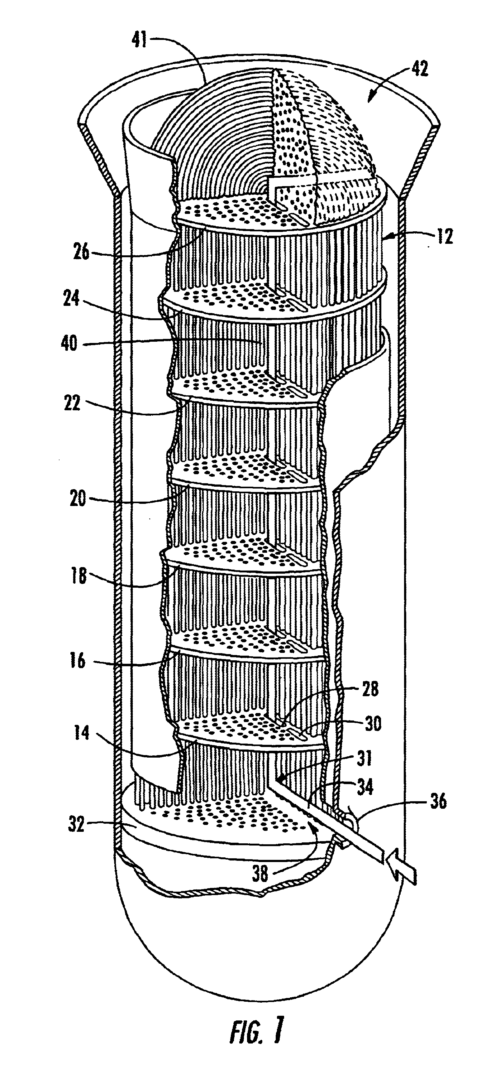
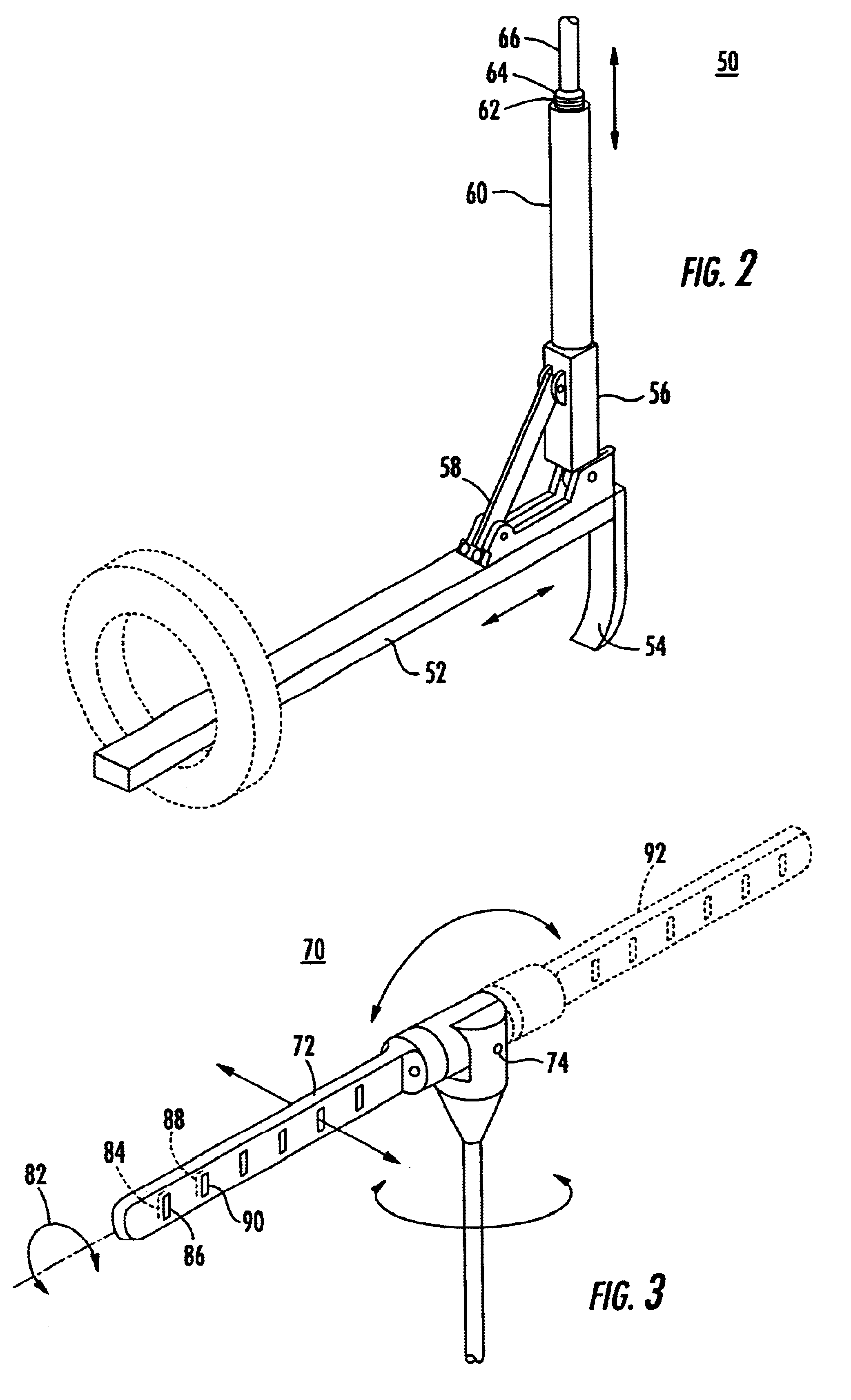
An alternative to the various rigid chain or rigid link embodiments described above is shown in FIG. 40. Extendable mast 770 is made of a material normally self-biased to form a tube as shown at 762 even though it can be fed off a flat roll 764. The material of mast 760 is typically a 0.010 spring-tempered stainless steel available from Spar Aerospace 9445 Airport Road, Brampton, Ontario, Canada. The natural aspect of the material is a 2" diameter tube with plenty of overlap. The tube may be reinforced along its length by guide sleeves such as sleeve 764 as required.

As shown in FIG. 40, mast 760 guides water line 770 and peripheral service lines 772 and 774 encased by jacketing material 776 up through the flow slots of the steam generator. Motor drive 778 drives this embodiment of the deployment system up through the flow slots. Motor drive 778 includes counter rotating drums 780 and 782 each driving planetary guide roller arrangement 784. As an alternative, two rolls of the mast ma...

embodiment 700

The mast shown in FIG. 40 may be used in conjunction with any of the rigid chains or rigid links described above including the rigid link embodiment 700, FIG. 37 as shown in FIG. 41 for additional support as the rigid links are extended upward to the top of the steam generator. Mast storage drum 782, FIG. 41 includes the roll or rolls or mast material and turning shoe 784 feeds the rigid links from outside the hand hole of the steam generator aqd ultimately up through the flow slots in the successive series of support plates.

In any embodiment of the elongated snake-like body of this invention, whether rigid chain or rigid embodiments or the mast material embodiment, or combinations thereof, the boom and telescopic cylinders of the prior art shown in FIG. 2 are eliminated and instead the elongated body is small enough so that it can be fed through the hand hole of the steam generator and through the flow slots in successive support plates. The body is also fully retractable to preven...


PUM


Abstract

An upper bundle steam generator cleaning, inspection, and repair system including a deployment support device receivable within the steam generator to raise a cleaning device, an inspection device, and/or a tool up to the upper bundles of the steam generator.

Description

This invention relates to an upper bundle cleaning, inspection, and repair system for a nuclear power plant steam generator.BACKGROUND OF INVENTIONSteam generators convert heat from the primary side of a nuclear power plant to steam on the secondary side so that the primary and secondary systems are kept separate. A typical generator is a vertical cylinder consisting of a large number of U-shaped tubes which extend from the floor or "tube sheet" of the generator. High temperature and pressure fluid from the reactor travels through the tubes giving up energy to a feedwater blanket surrounding the tubes in the generator creating steam and ultimately power when later introduced to turbines.Steam generators were designed to last upwards of forty years but in practice such reliability figures have proven not to be the case. The problem is that sludge from particulate impurities suspended in the feed-water forms on the tubes which greatly affects the efficiency of the generator and can ev...

Claims


Application Information

Patent Timeline
IPC IPC(8): F22B37/00F22B37/48F28G3/00F28G3/16F28G15/00F28G15/04
CPCF22B37/483F28G3/16F28G15/04
Inventor ASHTON, III, AUGUSTUS J.LOVETT, J. TIMOTHYFISCHBACH, DANIELRUGGIERI, STEVEN K.BRIGHTMAN, ALANJENS, STEVEN
Owner FOSTER-MILLER
Why Eureka
Try Eureka