Plastic pipe coupling system

a coupling system and plastic pipe technology, applied in the direction of hose connections, couplings, branching pipes, etc., can solve the problems of requiring destructive techniques, unable to allow rotational or axial misalignment, and unable to adjust the relative motion of parts, etc., to achieve the effect of simple disassembly and easy manual operation

Inactive Publication Date: 2004-01-13
WRAITH MATTHEW WILLIAM +2
View PDF14 Cites 21 Cited by
  • Summary
  • Abstract
  • Description
  • Claims
  • Application Information

AI Technical Summary

Benefits of technology

The pipe and coupling system of this invention is simply and easily assembled together to provide a stable and reliable locking engagement.
An important aspect of the present invention is that disassembly is simple. Partial disassembly of the coupling joint in order to adjust the rotational or axial alignment of the coupling with mating elements in the pipe string or replacement of components is easily accomplished. Slide the support ring over the pipe away from the coupling. Rotate or translate the coupling to the desired location. Slide the support ring back over the coupling. Total disassembly of the current invention can be easily manually accomplished by following the reverse order of the assembly. Slide the support ring off the coupling. Pull the coupling free of the pipe. Remove the support ring.

Problems solved by technology

(a) The solvents typically have a short working time typically about ten seconds. Once the solvent has set, relative motion of the parts is not possible.
(b) A solvent bond does not allow for any rotational or axial misalignment of the pipe joints. Misalignment can occur when assembling a pipe string that has an elbow, "T", "Y" or other geometry which requires specific rotational alignment.
(c) Disassembly of the parts after the solvent has set requires destructive techniques. The fittings must be cut off and a new fitting added.
(d) The mating surfaces which are to be solvent welded need to be clean and dry before application of the solvent.
(e) Before testing the system for integrity of a sealed connection the solvent must be completely cured.
(f) The unused solvent hardens over time until it is no longer usable.
(h) The solvent is difficult to use.
The threaded caps on the solvent cans can be difficult to open particularly if any solvent has dripped onto the threaded surfaces.
(i) Use of solvents for joining pipe components is unpleasant, and potentially hazardous.
The fumes represent a health hazard and are unpleasant.
The solvents can be extremely flammable and can cause damage to the environment.
(a) Couplings that require a gasket for sealing are very expensive and hence are rarely used for residential irrigation.
(b) These couplings are dimensionally large making them difficult to incorporate in pipe or tube strings. The increase in diameter can make it difficult to put many pipe strings in an irrigation trench such as those for residential sprinkler systems that are typically limited in size.
For all of these patents, repairs are very difficult, that is, in order to repair a broken section without the use of a coupling, the entire pipe must be replaced.
Additionally these patents suffer from a combination of the following problems: requires a complex, integral end connection that can not accommodate custom lengths, requires a gasket or solvent for sealing, does not include a press fit outer ring for support of the coupling under bending loads, requires tight tolerancing.
U.S. Pat. No. 5,918,914 and U.S. Pat. No. 5,662,360 have complex, integral end connections, require gaskets for sealing, and lack support for bending loads.
U.S. Pat. No. 5,078,430 has a complex, preformed, integral end connection, can not accommodate custom lengths, and requires a gasket for sealing.
U.S. Pat. No. 4,875,714 has a complex, preformed, integral end connection, requires tight tolerancing, can not be easily disassembled, and can not accommodate custom lengths.
U.S. Pat. No. 4,779,902 and U.S. Pat. No. 3,784,235 require a gasket or adhesive for sealing, can not accommodate custom lengths, and can not be easily repaired without the use of a coupling.
U.S. Pat. No. 3,217,400 can not be easily repaired or disassembled, and does not have an outer ring to support against bending loads.
(a) Fabrication of the pipe or tubing is complicated. The pipe can not be simply extruded but requires additional machining or other laborious fabrication process.
(b) Key components can not be easily fabricated in the field so they are impractical for applications which require customized pipe lengths.
(c) The joint is mechanically weak in bending.
(d) Relatively tight tolerancing is required between the mating surfaces.
(e) The parts generally can not be easily disassembled.
(f) Repair of a broken section requires the replacement of the entire pipe.
Patents that feature couplings can be complex.

Method used


Image

  • Plastic pipe coupling system
  • Plastic pipe coupling system
  • Plastic pipe coupling system

Examples


Embodiment Construction

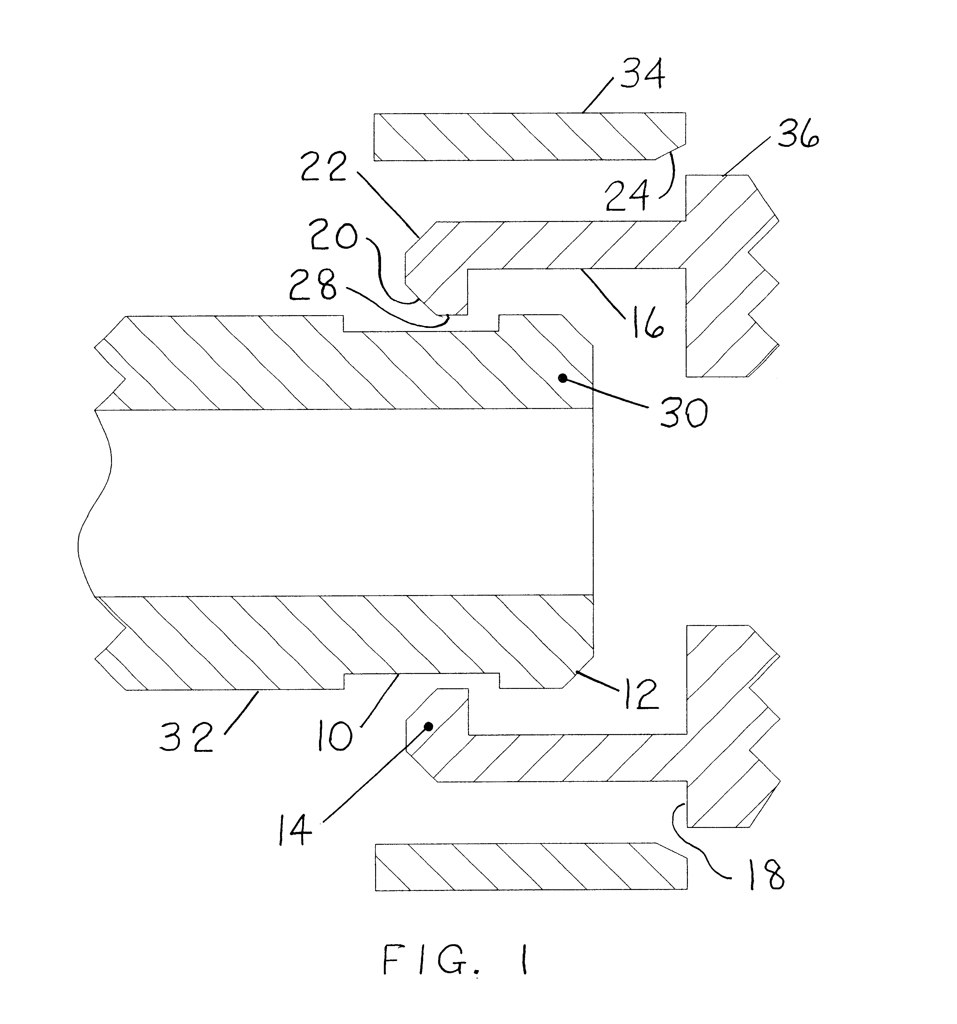
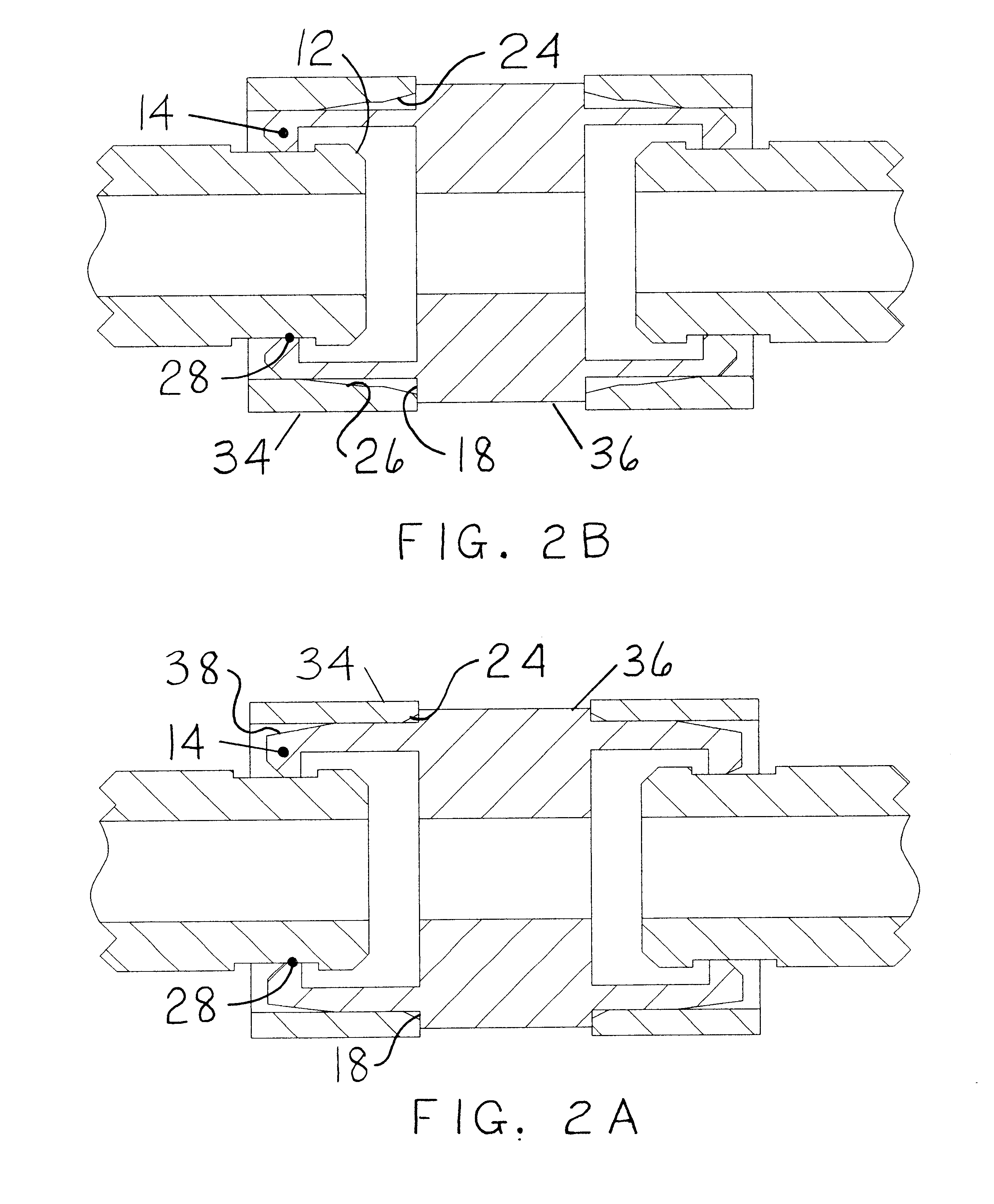
A typical embodiment of the pipe coupling system of the present invention is illustrated in FIG. 1 (exploded view). The invention comprises a pipe or tube 32, a support ring 34, and a joint or coupling 36. FIGS. 2A and 2B show the final assembly for two different configurations of the present invention. FIGS. 3A, 3B, 3C illustrate some of the many configurations in which the coupling of the present invention can be employed.

Pipe 32 is typically made from schedule 40 polyvinyl chloride pipe of the type commonly used for irrigation. Other options exist including but not limited to fabricating the pipe from polyvinyl chloride conduit or thicker walled schedule 80 polyvinyl chloride pipe. The pipe is preferably made from polyvinyl chloride but other plastic materials having similar characteristics of strength and flexibility may be employed. The pipe may range in diameter from about one half inch to over three inches and have a substantial wall thickness to withstand internal pressure o...


PUM

PropertyMeasurementUnit
working timeaaaaaaaaaa
diameteraaaaaaaaaa
diameteraaaaaaaaaa

Abstract

A plastic pipe coupling system including a female coupling and a support ring. A circumferential groove is molded or cut into the outer diameter of a plastic pipe. The female coupling includes a reduced diameter portion with a coupling rib at the free end. The ends of the pipe, coupling, and support ring are beveled in order that the ends pressed together engage and by the slight resiliency of the plastic construction permit the slight expansion and contraction of the ends to provide a locking interfit of the respective groove and rib at the two ends. There is an interference fit between the support ring and the coupling so that a radial preload is induced when the support ring is assembled onto the coupling. The inner surface of the sleeve or the outer surface of the coupling is tapered for ease of installation of the support ring over the coupling and to provide radial support to keep the coupling in the groove. Installation of the support ring over the female coupling results in a mechanically strong joint under axial and bending loads. Additionally, the joint is water tight under pressure without the use of a rubber gasket or solvent.

Description

Not Applicable.Not Applicable.REFERENCE TO A MICROFICHE APPENDIXNot Applicable.The present invention relates generally to plastic pipe systems or tubes of the type used particularly but not exclusively for irrigation systems, potable water, sewage, electrical power lines, and for any structures made from pipe or tube components which are assembled together.Plastic pipe systems formed from polyvinyl chloride, chlorinated polyvinyl chloride, polyethylene and other plastic materials are widely used for a variety of applications at the present time. With the advent of plastic pipe materials a need has existed for connecting lengths of pipe together to form a string of pipes or a structure.Currently there are several methods employed for joining plastic pipe or tubing strings. The most commonly used methods feature use of solvents and couplings, or specialized couplings, which include gaskets when a fluid seal is desired, or pipes with integral end connections.In the first case, a solven...

Claims


Application Information

Patent Timeline
Patent Type & Authority Patents(United States)
IPC IPC(8): F16L37/00F16L37/084F16L41/02
CPCF16L37/0841F16L37/0847F16L41/021
Inventor WRAITH, MATTHEW WILLIAMCOSTA, MICHAEL ALANPASTRONE, RONALD LOUIS
Owner WRAITH MATTHEW WILLIAM
Why Eureka
Try Eureka