Stripping process with horizontal baffles

a technology of horizontal baffles and stripping process, which is applied in chemical/physical processes, metal/metal-oxide/metal-hydroxide catalysts, and combustible gas purification/modification, etc. it can solve the problems of large surface area of the particles employed in the fcc process, significant amount of hydrocarbons being withdrawn from the reaction zone with the catalyst, and hotter regenerator temperatures

Inactive Publication Date: 2004-01-20
UOP LLC
View PDF17 Cites 40 Cited by
  • Summary
  • Abstract
  • Description
  • Claims
  • Application Information

AI Technical Summary

Benefits of technology

It is another object of this invention to increase the efficiency of stripping in a baffle style stripping vessel.
It is a further object of this invention to obtain a method and apparatus that provides a more complete and reduced utilization of stripping medium.
Additional objects, embodiments and details of this invention are given in the following detailed description of the invention.

Problems solved by technology

However, the catalyst particles employed in an FCC process have a large surface area, which is due to a great multitude of pores located in the particles.
Although the quantity of hydrocarbons retained on each individual catalyst particle is very small, the large amount of catalyst and the high catalyst circulation rate which is typically used in a modern FCC process results in a significant quantity of hydrocarbons being withdrawn from the reaction zone with the catalyst.
Greater concentrations of hydrocarbons on the spent catalyst that enters the regenerator increase its carbon-burning load and result in hotter regenerator temperatures.
However, because the sloped trays each occupy substantial elevation, they limit the number of trays that can be installed in a given height of a stripping vessel.
This makes hydraulics through the stripping vessel more difficult to control.
Moreover, erosion occurs through the jets which are higher on the baffle than through jets that are lower on the baffle because of the velocity differential.
Consequently, the variously eroded holes exacerbate the difficulty in controlling hydraulics.
On the other hand, setting baffles at a smaller slope will result in catalyst accumulation on top of the baffle unless fluidization over the baffle is increased, which could require increasing the flow rate of stripping medium.
In the case of steam, the costs include capital expenses and utility expenses associated with supplying the steam and removing the resulting water via downstream separation facilities.
Where there is not adequate supply or treatment capacity, the costs associated with raising the addition of stripping medium can be significant.
Moreover, it is not possible to simply increase stripping efficiency or capacity by accepting the economic penalties associated with the use of increasing amounts of steam.
At some point, the typical stripping vessel that operates with baffles becomes limited by the amount of catalyst flux moving through the stripping vessel.
Also, high levels of combined nitrogen, such as found in shale-derived oils, will increase the coke level on spent catalyst.
Processing of heavier feedstocks, such as deasphalted oils or atmospheric bottoms from a crude oil fractionation unit (commonly referred to as reduced crude) results in an increase in some or all of these factors and therefore causes an increase in the coke level on spent catalyst.
This results in an increase in the temperature of the catalyst and the generation of a large amount of hot gas which is removed from the regeneration zone as a gas stream referred to as a flue gas stream.
Thus, even when the largest number of holes were provided, large areas of unperforated sections still exist over the sloped surface.

Method used


Image

  • Stripping process with horizontal baffles
  • Stripping process with horizontal baffles
  • Stripping process with horizontal baffles

Examples


Embodiment Construction

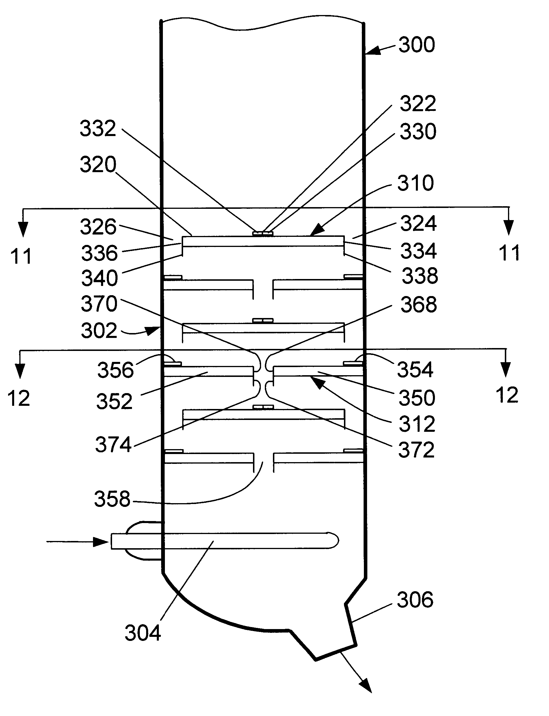
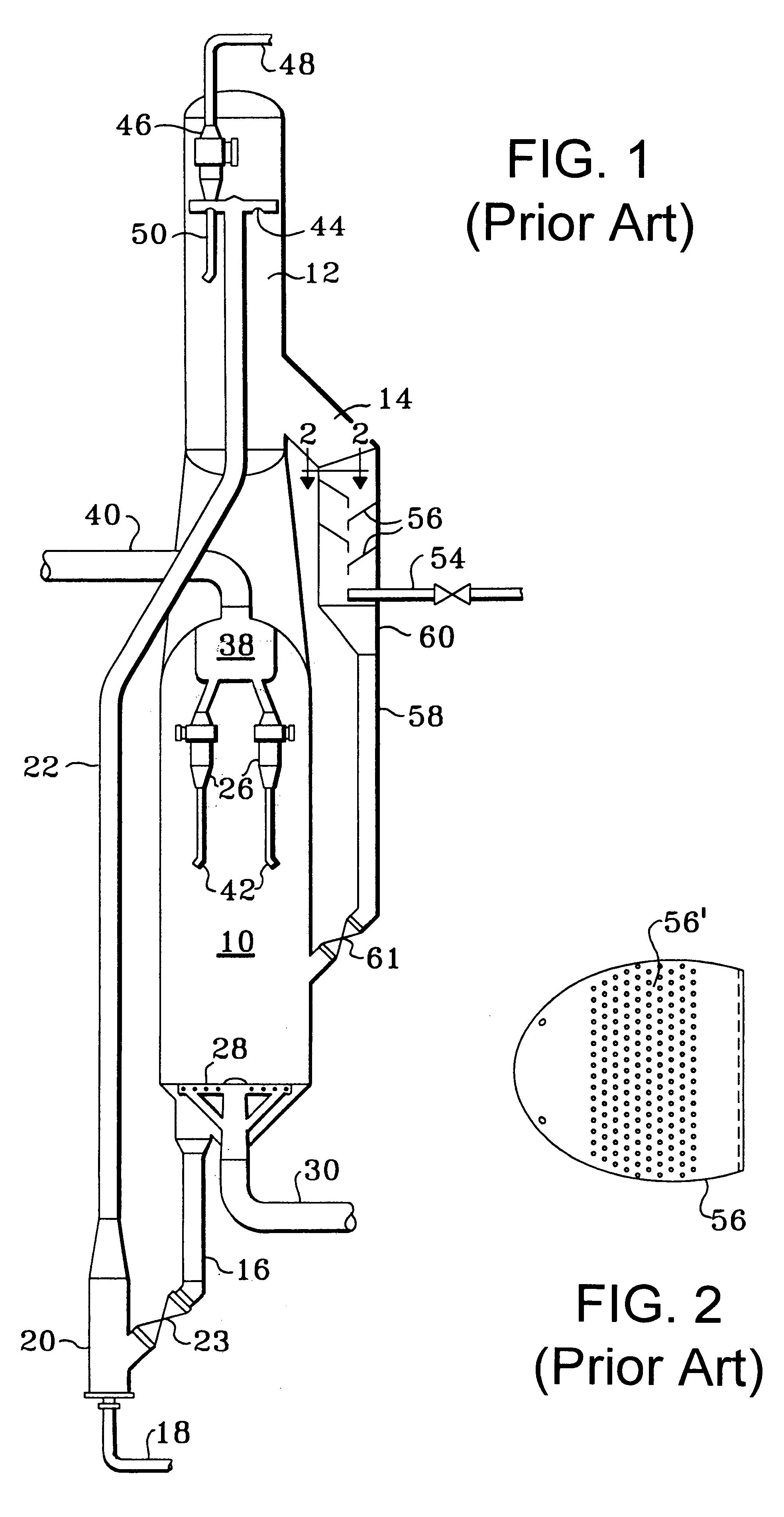
series of tests was conducted to more fully demonstrate the unique and unexpected change in stripping performance that results from the use of horizontal baffles with downcomers over using conventional, sloped baffles. A test apparatus was constructed to measure conventional stripping performance from clear plastic panels to permit visual observation. The test apparatus modeled a 19.degree. sector from a conventional cylindrical stripping arrangement similar to that shown in FIGS. 1 and 2 having a transverse cross-sectional area of about 0.19 m.sup.2 (2 ft.sup.2). Inner and outer stripping baffles having a trapezoidal shape and a projected horizontal area of about 0.09 m.sup.2 (1 ft.sup.2) were alternately placed at inner and outer locations of the apparatus to complete the model of a sector of a stripping vessel. A total of four effective outer baffles and three effective inner baffles were used with about a 97 cm (38 inch) spacing between adjacent outer baffles and between adjacen...


PUM

PropertyMeasurementUnit
angleaaaaaaaaaa
temperatureaaaaaaaaaa
boiling pointsaaaaaaaaaa

Abstract

A baffle-style stripping arrangement for an FCC process having substantially horizontal stripping baffles is disclosed. The stripping baffles comprise a perforated section and a downcomer section which generates transverse movement of catalyst across the baffle to ensure adequate vertical movement of stripping media. The perforated section is covered with stripping openings to provide improved stripping efficiency and catalyst flux through the stripping vessel. The perforated section may comprise a grate. Baffles may also include an imperforate section which is vertically aligned with a downcomer section of a superjacent baffle.

Description

This invention relates to processes and apparatuses for the fluidized contacting of catalyst with hydrocarbons. More specifically, this invention relates to processes and apparatuses for stripping entrained or adsorbed hydrocarbons from catalyst particles.DESCRIPTION OF THE PRIOR ARTA variety of processes contact finely divided particulate material with a hydrocarbon containing feed under conditions wherein a fluid maintains the particles in a fluidized condition to effect transport of the solid particles to different stages of the process. Catalyst cracking is a prime example of such a process that contacts hydrocarbons in a reaction zone with a catalyst composed of finely divided particulate material. The hydrocarbon feed fluidizes the catalyst and typically transports it in a riser as the catalyst promotes the cracking reaction. As the cracking reaction proceeds, substantial amounts of hydrocarbon, called coke, are deposited on the catalyst. A high temperature regeneration within...

Claims


Application Information

Patent Timeline
Patent Type & Authority Patents(United States)
IPC IPC(8): B01J8/28B01J20/34B01J20/30B01J8/34B01D53/10B01D53/06B01J8/24B01J8/00B01J38/00B01J38/04C10G11/00C10G11/18
CPCB01D53/10B01J8/0055B01J8/008B01J8/28B01J38/04C10G11/18C10G11/182B01J8/34C10G2300/4093B01J2208/0084
Inventor KOEBEL, JEFFREY P.HEDRICK, BRIAN W.PUPPALA, KALIDAS
Owner UOP LLC
Why Eureka
Try Eureka