Obviously, the problem of such an error path filter is that the
white noise is outputted from a
white noise generator 130 through the loud speaker to the outside of the duct upon the calculation of the coefficient.
It is also a problem that the coefficient thus calculated of the error path filter 230 is hereafter to be fixed upon the active noise control as shown in FIG. 30.
This simulating operation with a lowered accuracy may have a bad influence on the accuracy maintenance of the coefficient of the noise control filter 220, whereby a sufficient quantity of the
noise reduction can not be obtained, and besides the noise control operation becomes unstable.
However, in such a circuit arrangement, as mentioned above, the overlap of the white noise outputted from the loud speaker 203 during the active noise control indicates that the active noise control apparatus becomes a new noise source.
However, since the setting of such a small step
gain causes a problem that a noise canceling performance is deteriorated in fixed-point arithmetic, which is practically left unsolved upon adopting an inexpensive fixed-point signal processor.
This measure of adding the perturbation is equivalent to the overlap of the white noise with the secondary noise, which can not solve the problem of the arrangement in FIG. 30.
However, it is a problem that the coefficient thus calculated of the
feedback control filter 210 is hereafter fixed naturally because the change of the characteristic within the duct 200 is fully expected.
This deterioration of the interception performance not only increases the danger of howling occurrence but also increases the estimated coefficient error of the noise control filter 220 and deteriorates the
noise reduction performance.
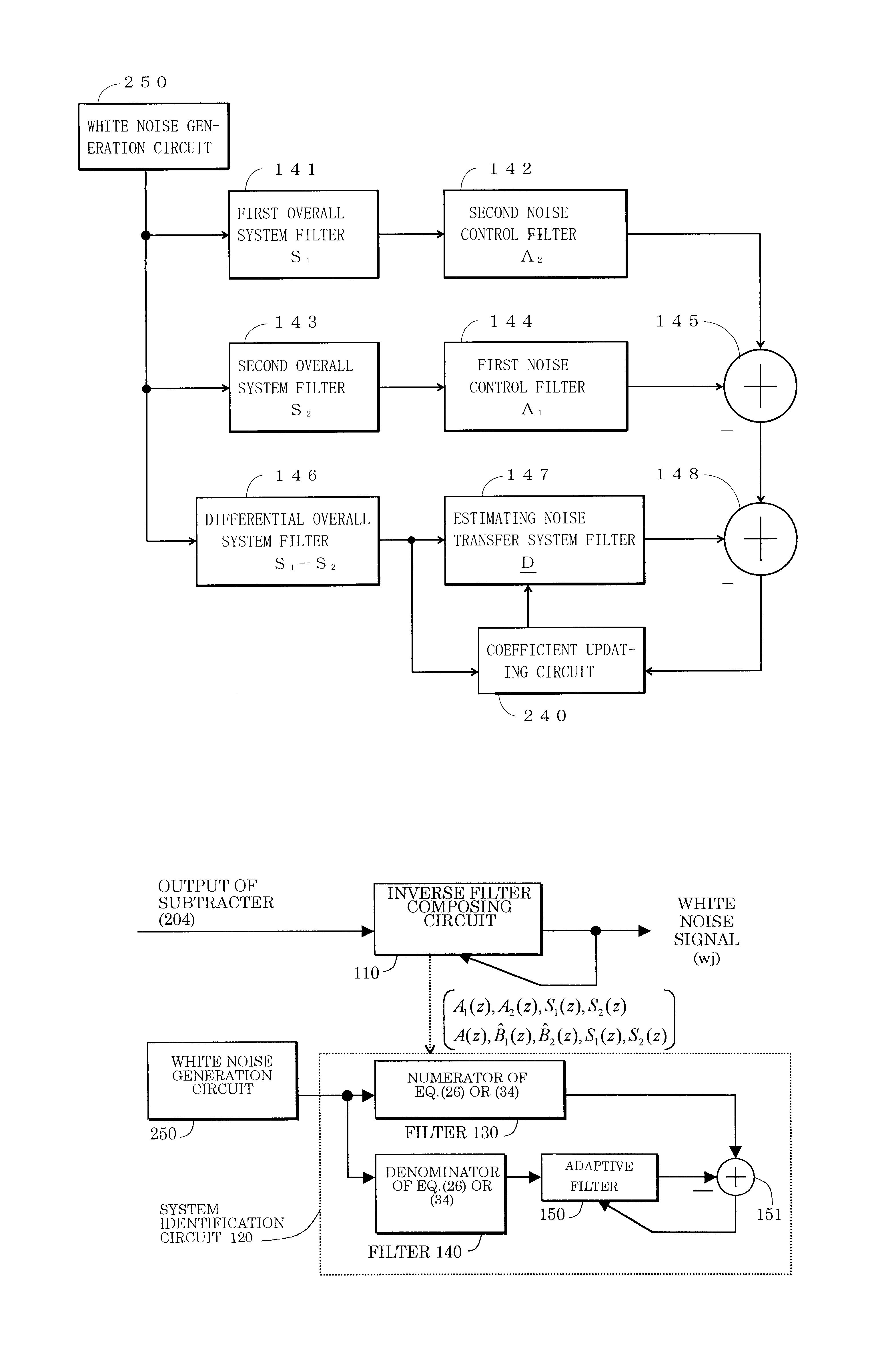
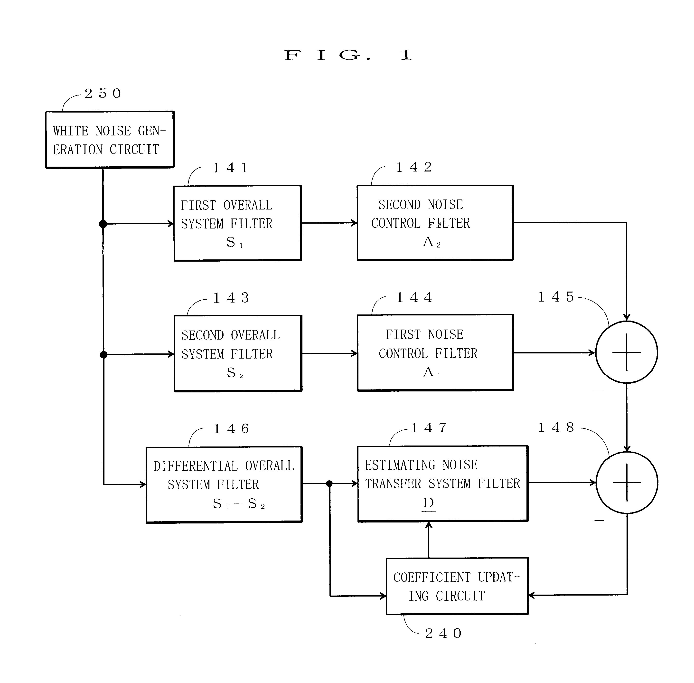
However, the defect of this method obviously lies on that a different kind of noise (white noise) from the white
noise generation circuit 250 introduced for reducing the noise is transmitted from the loud speaker 203.
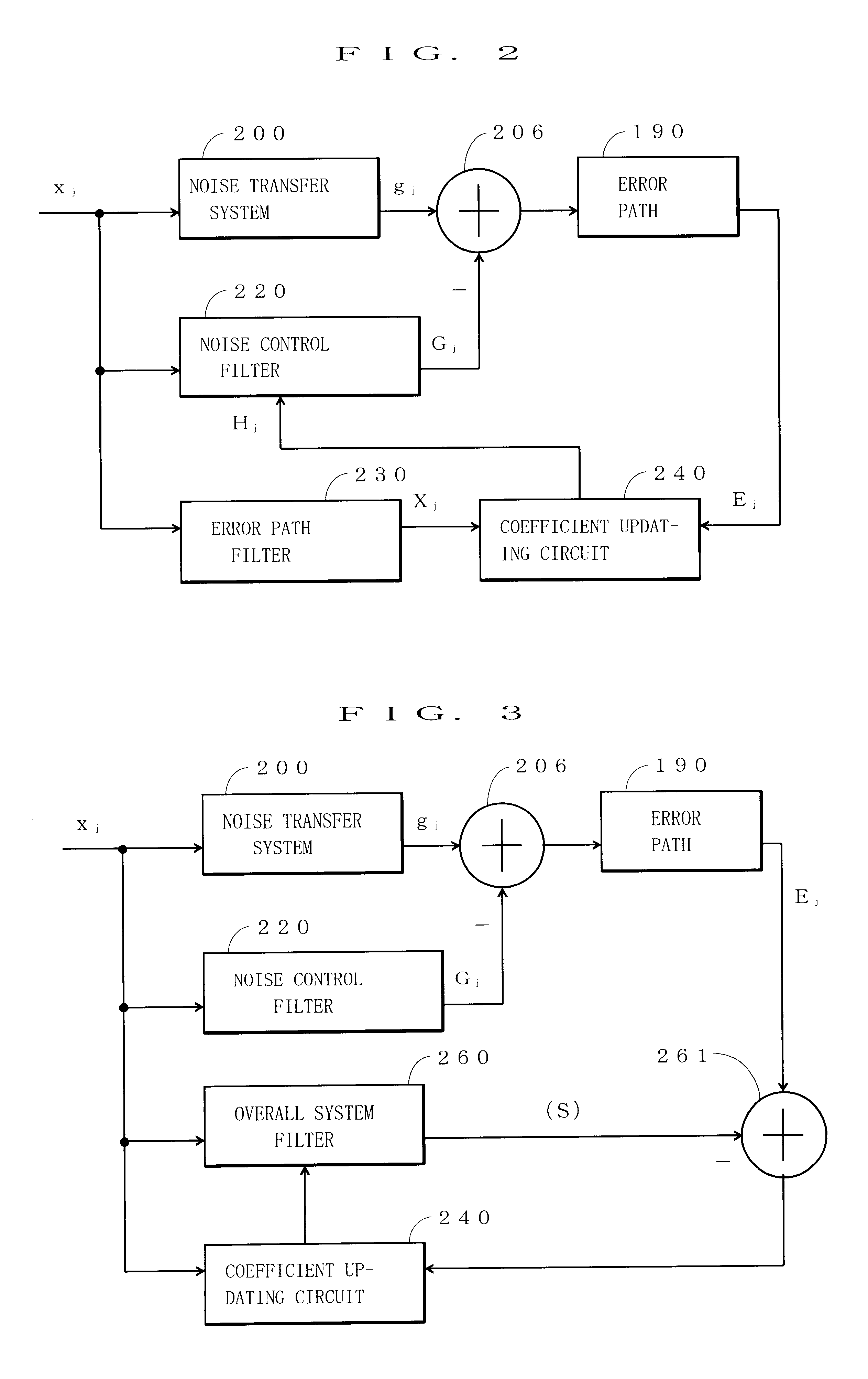
The problem in the active noise control of the feedback type arises from the synthesized noise g.sub.j being generated based on the noise w.sub.j to be controlled.
However, the problem in this case is that the control principles of the active noise control apparatuses of the feedback type in FIGS. 35 and 38 both premise B(z)=B(z).
Generally, in the estimate of the
impulse response of the feedback path the error is inevitable, so that it is fully expected that the response changes with time.
Also, according to the analysis, even if the step
gain is made small, the stability can not be completely guaranteed.
However, in the apparatus mentioned in the Japanese
Patent Application No.9-239776 (Japanese Patent Publication Laid-open No.11-85165) as mentioned above, that "it is necessary that the
inverse filter W.sup.-1 (z) of the filter W(z) which generates the noise x.sub.j is formed before starting the active noise control" makes an issue.

