Concentrating photovoltaic cavity converters for extreme solar-to-electric conversion efficiencies

a photovoltaic cavity and conversion efficiency technology, applied in thermal-pv hybrid energy generation, machines/engines, control devices, etc., can solve the problems of wasting the remainder of available energy outside of their limited spectral response, and wasting the excess energy of photons

Inactive Publication Date: 2004-02-10
UNITED INNOVATIONS
View PDF9 Cites 197 Cited by
  • Summary
  • Abstract
  • Description
  • Claims
  • Application Information

AI Technical Summary

Benefits of technology

(c) at least one wavelength filter associated with each solar cell, wherein the wavelength filter is selected from the group consisting of Rugate filters and a combination of Rugate filters and stack interference filters, thereby providing selective transmission and reflection of incident solar radiation to assist in maximizing the utilization of a region of the solar spectrum by solar cells having an appropriate bandgap.

Problems solved by technology

State-of-the-art single junction solar arrays as well as concentrators using single junction solar cells utilize only a limited portion of the available solar spectrum, thereby wasting the remainder of available energy outside of their limited spectral response.
The limitation is caused mainly by two basic "photon loss" mechanisms within the cells, namely, (1) loss by longer wavelengths and (2) loss by excess energy of photons.
The excess energy raises the temperature of the solar cell and degrades its performance.
Thus, even high quality cells with excellent quantum efficiencies, such as GaAs, exhibit relatively modest conversion efficiencies since they cannot respond to more than a relatively small portion of the incident spectrum.
Under actual operating conditions, the MJ concentrator system performance can drop more than 12 to 15% (absolute) against the bare cell performance and defeat the use of high efficiency MJ cells.
Some of the major concentration-related performance losses in MJ cells are caused by the following shortcomings: absorption of light in the top cells, chromatic aberrations caused by the concentrator optics, flux non-uniformity on the cells, limited heat removal from the top cells, current limitation in the cells, series resistance, shadowing losses due to finger contacts on the cells, and limited acceptance angle for photon incidence on the cells.
MJ cells, however, are more vulnerable to most of these performance-limiting factors.
The relative deterioration of MJ cells becomes worse as the number of junctions increases.
Several authors in the field have predicted that for vertically stacked or monolithically-grown systems, limited improvements are expected beyond triple-junction cells.
In spite of extensive efforts, this material remains elusive.
Thus, even the best bandgap matched sub-cell cannot result in a multi-junction cell if their lattices mis-match.
These apparent limitations represent a formidable bottleneck in the development of high and very high efficiency (and therefore cost-competitive) concentrator systems in the near future.
To the knowledge of the present inventor, this concept has never come to a closure, presumably due to extreme difficulties encountered with the associated optics.
A thorough literature search has shown that in the past, the very promising method of spectral splitting and simultaneous use of discrete solar cells with different bandgaps has never reached its potential capacity and the technology was never exploited fully.

Method used


Image

  • Concentrating photovoltaic cavity converters for extreme solar-to-electric conversion efficiencies
  • Concentrating photovoltaic cavity converters for extreme solar-to-electric conversion efficiencies
  • Concentrating photovoltaic cavity converters for extreme solar-to-electric conversion efficiencies

Examples


Embodiment Construction

Reference is now made in detail to a specific embodiment of the present invention, which illustrates the best mode presently contemplated by the inventor for practicing the invention. Alternative embodiments are also briefly described as applicable.

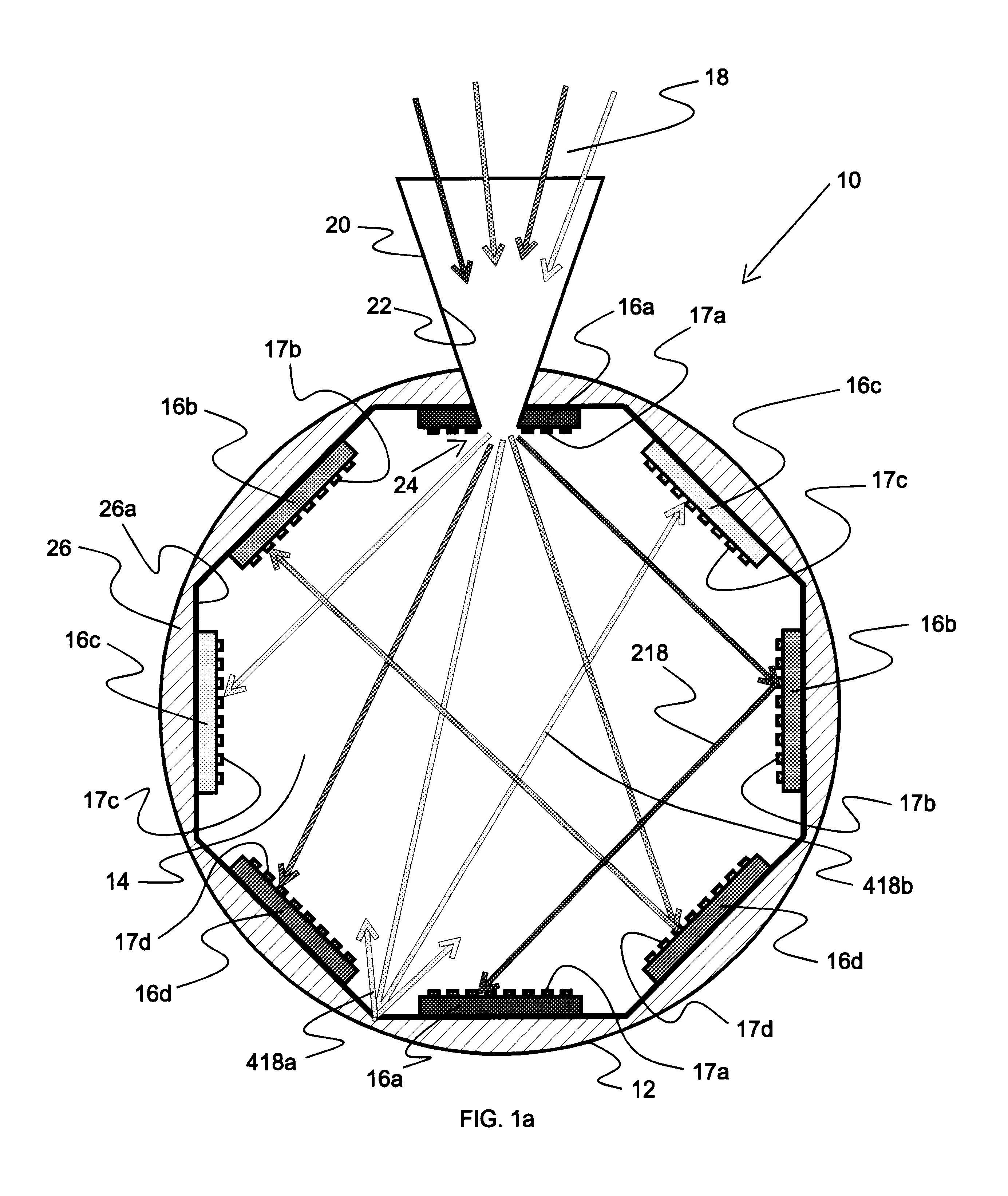
The invention herein is directed to the performance of a photovoltaic cavity converter (PVCC) module designed for a concentration in the range of 500 to over 1000 suns and a power output range of a few kilowatts to 50 KW.sub.e when combined with a primary dish and a secondary concentrator. A 1.5 KW prototype unit is presently being developed for use at the NREL High-Flux Solar Furnace (HFSF). The module herein is also expected to find use in, for example, DOE's Concentrating Solar Power (CSP) program to develop systems in the 1 to 5 kW.sub.e and 10 to 30 kW.sub.e size ranges based on reflective optics. A typical power range is about 30 to 50 kiloWatts. Connecting a plurality of such modules together in a power plant permits power generati...


PUM


Abstract

A concentrating photovoltaic module is provided which provides a concentration in the range of about 500 to over 1,000 suns and a power range of a few kW to 50 kW. A plurality of such modules may be combined to form a power plant capable of generating over several hundred megaWatts. The concentrating photovoltaic module is based on a Photovoltaic Cavity Converter (PVCC) as an enabling technology for very high solar-to-electricity conversions. The use of a cavity containing a plurality of single junction solar cells of different energy bandgaps and simultaneous spectral splitting of the solar spectrum employs a lateral geometry in the spherical cavity (where the cell strings made of the single junction cells operate next to each other without mutual interference). The purpose of the cavity with a small aperture for the pre-focused solar radiation is to confine (trap) the photons so that they can be recycled effectively and used by the proper cells. Passive or active cooling mechanisms may be employed to cool the solar cells.

Description

The present invention is related generally to solar power, employing photovoltaic cells, and, more particularly, to novel concentrating photovoltaic modules that achieve extremely high efficiencies.State-of-the-art single junction solar arrays as well as concentrators using single junction solar cells utilize only a limited portion of the available solar spectrum, thereby wasting the remainder of available energy outside of their limited spectral response. The limitation is caused mainly by two basic "photon loss" mechanisms within the cells, namely, (1) loss by longer wavelengths and (2) loss by excess energy of photons. In the former case, photons with energy smaller than the "energy bandgap" or "forbidden gap" E.sub.g (direct bandgap semiconductor) or E.sub.g -E.sub.phonon (indirect bandgap semiconductors where E.sub.phonon is the phonon quantum of energy) cannot contribute to the creation of electron-hole pairs. In the latter case, in the spectrum range of interest, one photon g...

Claims


Application Information

Patent Timeline
Patent Type & Authority Patents(United States)
IPC IPC(8): H01L31/00H01L31/052
CPCH01L31/052H01L31/0547Y02E10/52H01L31/0521H01L31/0549H02S40/44Y02E10/60
Inventor ORTABASI, UGUR
Owner UNITED INNOVATIONS
Why Eureka
Try Eureka