Method and apparatus for heating and cooling of buildings

a technology for heating and cooling buildings and buildings, applied in lighting and heating apparatus, heating types, applications, etc., can solve the problems of low thermal conduction, high investment cost, and inability to meet the needs so as to achieve the lowest heat extraction efficiency, reduce the heat-pump heat-pump capacity, and enhance the effect of small-scale heat-pump and thermal storag

Inactive Publication Date: 2004-02-17
GETHER
View PDF15 Cites 23 Cited by
  • Summary
  • Abstract
  • Description
  • Claims
  • Application Information

AI Technical Summary

Benefits of technology

Another advantage of the invention is that the heat extraction capacity of the heat-pump may be reduced compared to conventional use of heat-pumps, since there is no longer a need to ensure a heat extraction capacity to cover the heat consumption at the coldest expected weather when the heat-pump also has the lowest heat extraction efficiency. Thus one can employ smaller and cheaper heat-pumps since they are always run at optimised conditions since the extra heat demand at the cold periods are covered by extraction of heat from the thermal store. Another advantage of the invention is that by use of relatively short term climate variations, one can employ relatively small sized thermal stores with moderate insulation means. Especially when compared to systems where the seasonal temperature variations are employed. Thus, the thermal stores according to the invention will be economically very competitive compared to conventional stores.
is that the heat extraction capacity of the heat-pump may be reduced compared to conventional use of heat-pumps, since there is no longer a need to ensure a heat extraction capacity to cover the heat consumption at the coldest expected weather when the heat-pump also has the lowest heat extraction efficiency. Thus one can employ smaller and cheaper heat-pumps since they are always run at optimised conditions since the extra heat demand at the cold periods are covered by extraction of heat from the thermal store. Another advantage of the invention is that by use of relatively short term climate variations, one can employ relatively small sized thermal stores with moderate insulation means. Especially when compared to systems where the seasonal temperature variations are employed. Thus, the thermal stores according to the invention will be economically very competitive compared to conventional stores.
The benefits of the opportunity to employ small scaled heat-pumps and thermal stores can be further enhanced by leading the used air from the houses / buildings to the heat pump for recovery of waste heat. That is, employing the heat-pump as a heat exchanger for reusing the waste heat in addition to the extraction of additional heat from outdoor air. This working principle is illustrated in FIG. 2, and will be thoroughly explained under the following

Problems solved by technology

However, there are a number of problems associated with this approach.
Rock and soil have a very low thermal conduction, thus the rock / soil needs a substantial amount of time to replace the heat extracted by the fluid medium.
And as a consequence the investment cost often becomes prohibitive for this type heat extraction.
However, there are problems with corrosion and fouling, especially in sea-water, and this solution is strictly restricted to buildings and houses in the vicinity (within 100 m) of open water.
Such solutions are very competitively priced, but has a major drawback in that they significantly looses effect when the demand for heat is largest.
Also, such solutions have encountered severe problems with freezing up of heat exchanger surfaces when the open-air temperature has fallen below +2.degree. C.
However, for cold climates the available solar radiation is less than for warmer climates while the need for heat is larger.
Thus this solution is also encumbered with prohibitive costs, and have therefore not found general use.

Method used


Image

  • Method and apparatus for heating and cooling of buildings
  • Method and apparatus for heating and cooling of buildings
  • Method and apparatus for heating and cooling of buildings

Examples


example 2

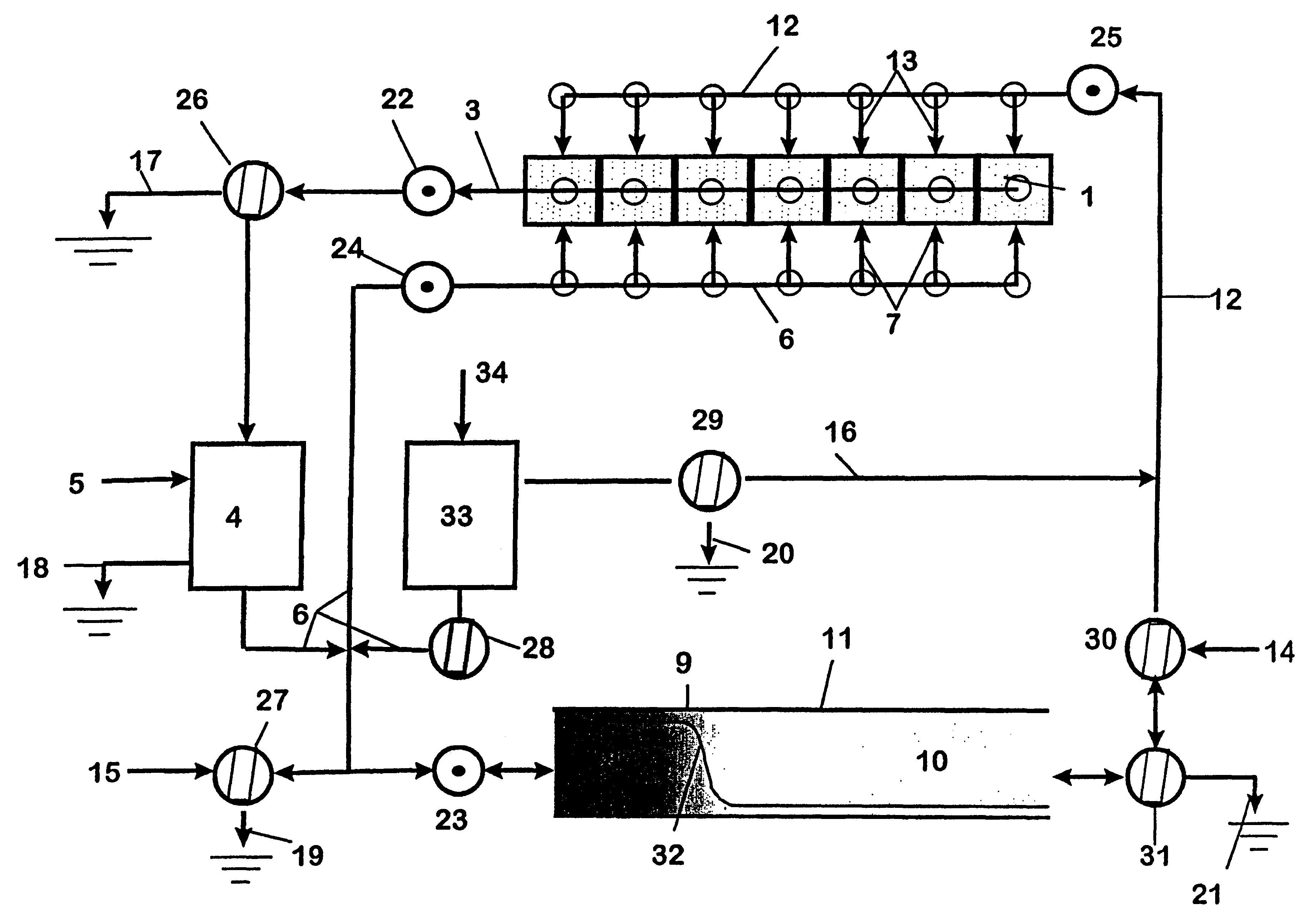
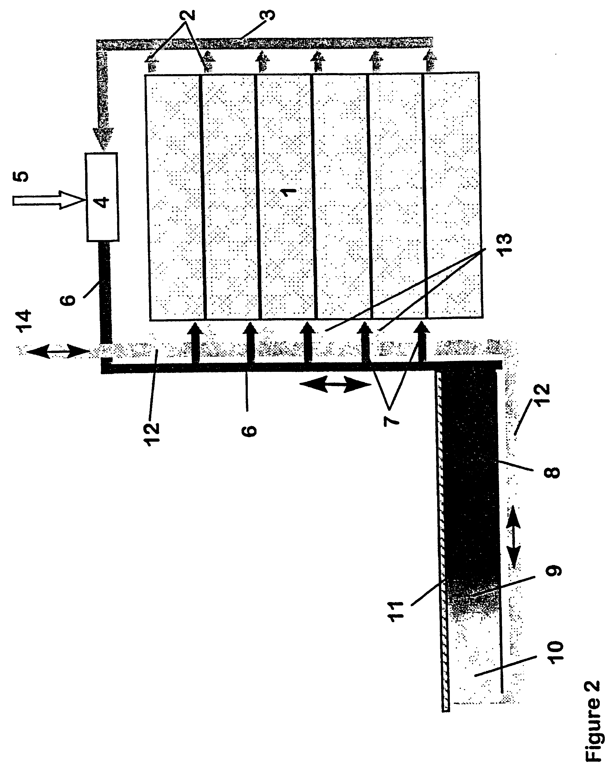
This example gives an example of a preferred embodiment of the invention that is suitable for cold climates and in some coastal climates where the need for active cooling is unlikely to occur. This embodiment is exactly similar to the embodiment of example 1, except that heat-pump 33, the right branch of duct 6 with 2-way flow diverter 28, and duct 16 with 2-way flow diverter 29 and discharge outlet 20 is omitted.

example 3

This example gives an example of a preferred embodiment of the invention that is suitable for warm climates where the need for active heating is unlikely to occur. This embodiment is exactly similar to the embodiment of example 1, except that heat-pump 4 with the left branch of duct 6 with 2-way flow diverter 26, fresh air inlet 5, and discharge outlet 20 is omitted.


PUM


Abstract

This invention relates to a method and apparatus for energy effective regulation of temperature and ventilation of one or more ventilation units of buildings, where one or more heat-pumps are used to exchange thermal energy between outdoor air and an indoor heat carrying fluid medium and where the heating and / or cooling of each ventilation units are achieved by distributing the indoor heat carrying fluid medium in each ventilation units, in such a manner that the natural short term variations in outdoor temperature due to passages of weather systems and the day / night variations is utilized to give the one or more heat-pumps optimized conditions such that they are only turned on for extracting outdoor heat which is delivered to the indoor heat carrying and distributing fluid medium at the relative warm periods in the case of warming the buildings, or only in the relative cold periods for cooling the heat carrying and distributing fluid medium for removal of indoor heat in the case of cooling the buildings, and that the thermal energy that is exchanged with the outdoor air is partly used to cover the ventilation units actual demand for heading or cooling while the remaining major part of the thermal energy is sent to a thermal store to cover the ventilation units heating or cooling demand during the subsequent periods where the natural weather conditions is less favorable for exchanging thermal energy from outdoor air by use of heat-pumps.

Description

This invention relates to a method and apparatus for heating and cooling (climate control) of buildings and houses, where a typically 5-15 day thermal storage is integrated with heat-pumps and ventilation to operate in a particularly optimised synergy.Large geographical areas in the world has a climate that generally goes through a seasonal change from a warm period in the summer to a cold period in the winter. This seasonal variation is naturally greatly dependent the local topography, whether there is an inland or coastal climate and the actual global latitude in question, but will nevertheless usually be of such an extent that buildings / houses needs means for cooling during the warm season and heating during the cold season in order to keep a comfortable indoor temperature of 20-22.degree. C. For example, in Norway the mean temperatures may vary from -5.degree. C. to +20.degree. C. over a year, while Mediterranean countries and large parts of USA may typically see mean temperatur...

Claims


Application Information

Patent Timeline
Patent Type & Authority Patents(United States)
IPC IPC(8): F24F5/00
CPCF24F5/0017Y02E60/147Y02E60/14
Inventor GETHER, J.O SLASHED.RGENGETHER, HARALD
Owner GETHER
Why Eureka
Try Eureka