
Flexible, self conforming, workpiece support system and accessories

a flexible support and self-conforming technology, applied in the direction of positioning apparatus, metal-working machine components, manufacturing tools, etc., can solve the problems of not allowing the removal of any clamping ram, affecting the performance affecting the operation of the clamping ram, etc., to achieve the effect of increasing the resistance force and increasing the magnetic for

Inactive Publication Date: 2004-02-24
GALAHAD
View PDF10 Cites 32 Cited by
  • Summary
  • Abstract
  • Description
  • Claims
  • Application Information

AI Technical Summary

Benefits of technology

A second aspect of the present invention is to provide a means to support the workpiece using a plurality of elongated support members, whereby the plurality of elongated support members may create a profile of the contact face of the workpiece.
A fifth aspect of the present invention is the ability to easily remove or install any of the said support members from the primary assembly of the invention.
A seventeenth aspect of the present invention is the ability to limit the height of the individual pistons during the contouring process.
A mechanism which can maintain the position of the elongated support members in a contoured position. Several options include a sliding single perforated plate to apply a clamping holding force, increasing the resistance force from a resistive member such as by increasing the magnetic force, and sealing a fluid within the above described molded member.

Problems solved by technology

The system does not allow the removal of any of the clamping rams.
Each of the above contouring support apparatuses is limited where they do not provide a means for easy removal or re-installation of any of the elongated support members.
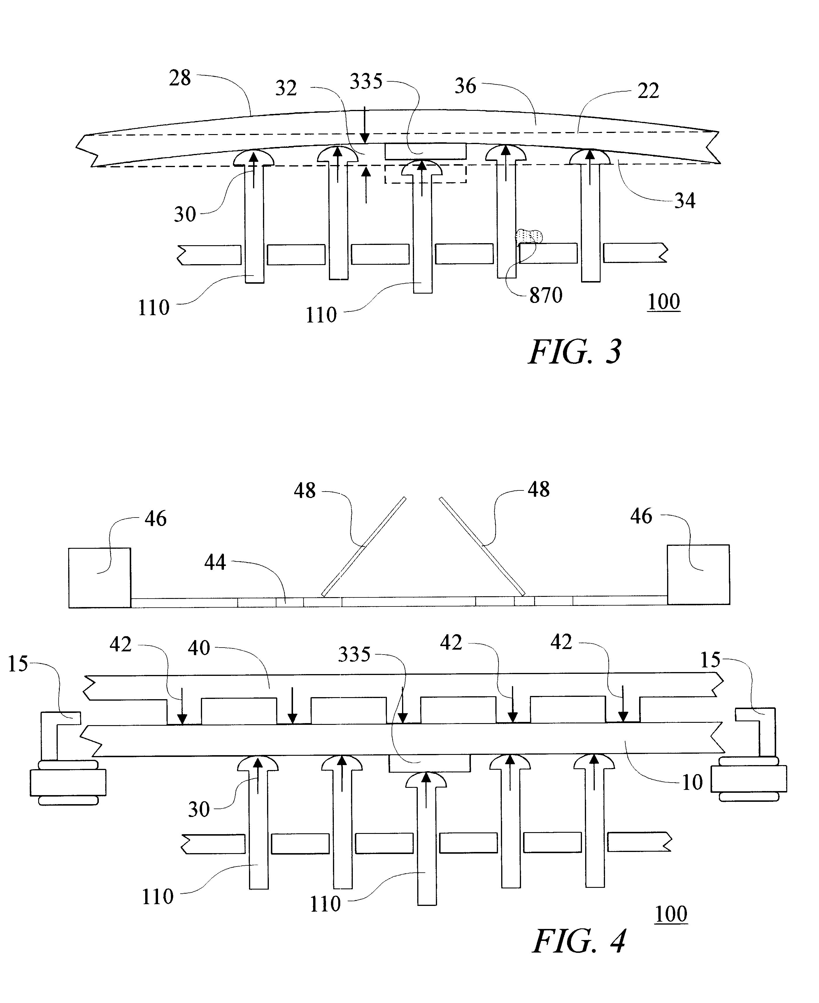
The flexible, self-conforming workpiece support systems disclosed in the parent applications, as well as similar apparatuses such as the cited arts may be subjected to harsh environments such as solder printing.

Method used


Image

  • Flexible, self conforming, workpiece support system and accessories
  • Flexible, self conforming, workpiece support system and accessories
  • Flexible, self conforming, workpiece support system and accessories

Examples


Embodiment Construction

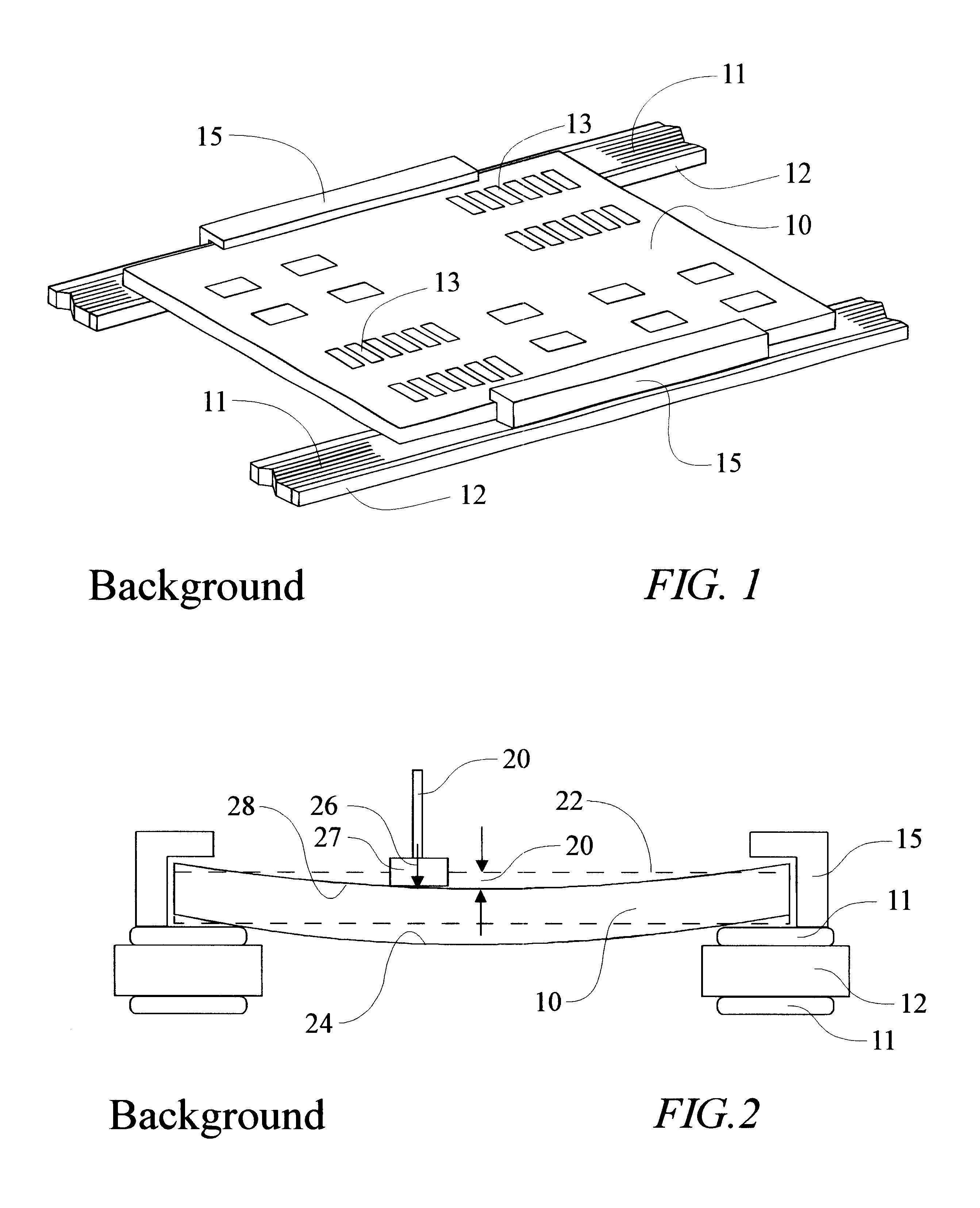
FIG. 1 is an isometric view of a PCA (module) 10 illustrating the workpiece 10 located on a conveyor belt 11 within the workstation (not shown). The workpiece 10 is transferred into and out of the workstation via a conveyor belt 11. The conveyor belt 11 rides along the conveyor rail 12. After transferring the workpiece 10 to the desired location within the workstation, the workpiece 10 is secured into location using a securing mechanism 15, in this case illustrated as clamps. Optionally, some workstations use vacuum, which is not shown in this figure. The workpiece 10 is secured to ensure accuracy throughout the operation of the workstation. One reason to secure the workpiece 10 into location is to maintain placement accuracy for various component locations 13.

FIG. 2 is a sectional side elevation illustrating a non-desirable deflection 20 of a workpiece 10 during the operation of a workstation. The workpiece 10 is located on the conveyor belt 11, as described by FIG. 1. The conveyor...


PUM


Abstract

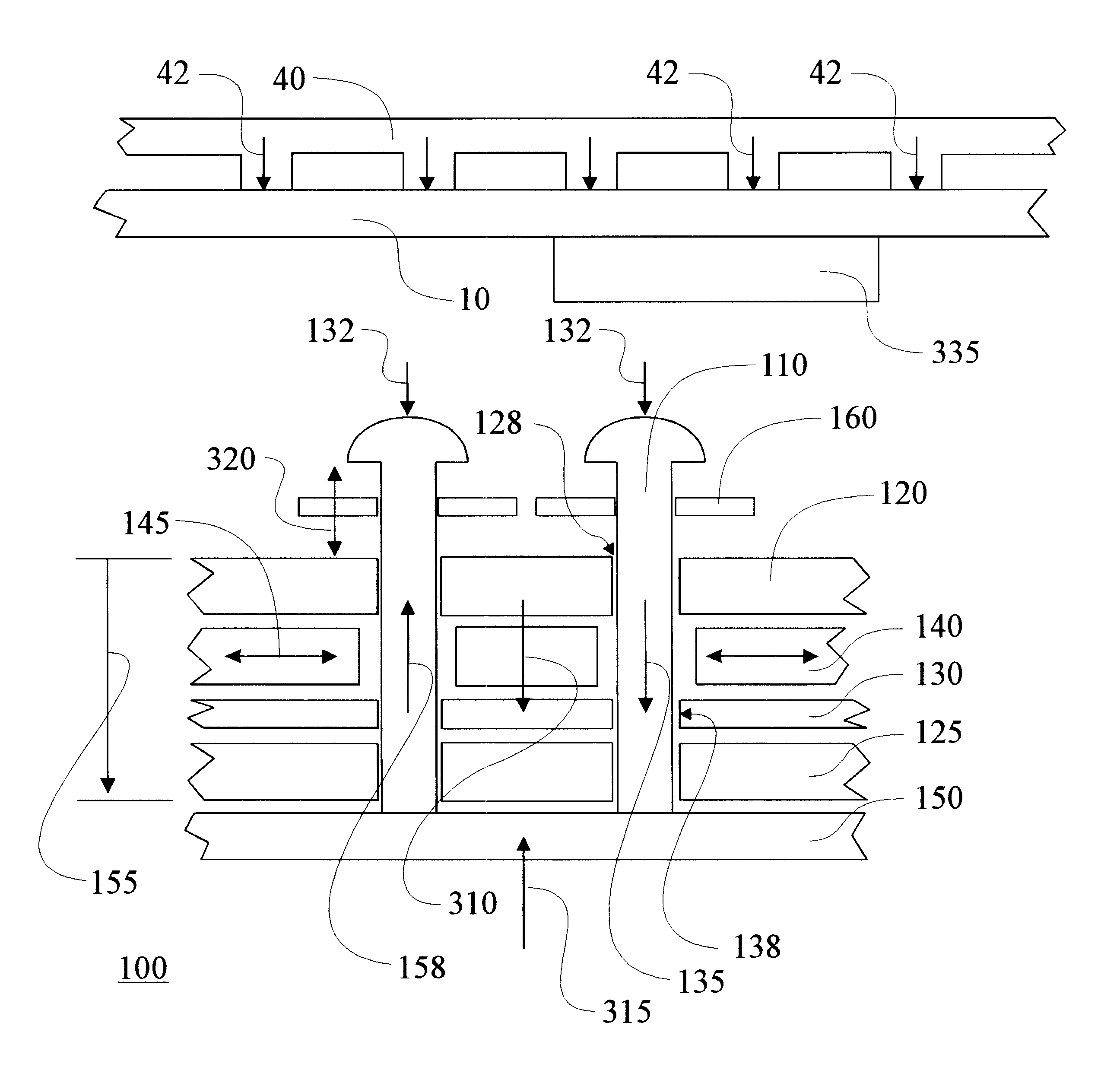
An apparatus and accessories are disclosed for a flexible support apparatus 100, 900 using elongated support members 110 to support a face of a workpiece 10 and respective protrusions 335. The elongated support members 110 are arranged through at least one plane of perforated material 120, where the elongated support members 110 are profiled against the workpiece 10 and respective protrusions 335. The profile of the elongated support members 110 is created by contacting forces 132 generated by bringing the workpiece 330 and the plurality of elongated support members 110 together. A holding force is then applied to the elongated support members 110 to support the workpiece 10 against forces applied by a workstation. Fluid 902 is used to raise expansion members to raise the plurality of elongate support members 110. A perforated plate 920 is used to control the flow of fluid 902 between a fluid cavity 910 and the plurality of expansion members 904. Accessories to improve performance and reliability include a protective collar for protection from foreign materials 870 (solder paste) and a reinforcing member 40, 44 to reinforce thin, flexible workpieces 10.

Description

FIELD OF THE INVENTIONThe present invention relates to accessories for flexible support systems using elongated support members that vary in position to support planer and / or three-dimensional workpieces.BACKGROUND OF THE INVENTIONNumerous manufacturing processes require a means to support a workpiece, without causing damage, so that an operation can be effected thereon, particularly an operation which applies a force or pressure to the workpiece, such as a printed circuit board (PCB) during printing or population. The face of the workpiece to be supported may not necessarily be planer, as demonstrated by the example of a two-sided electronics assembly; at least one application requires tooling to support a three dimensional face.There are several known apparatuses, which utilize elongated support members, which conform to the profile of the contact surface of the workpiece.Thyberg et al. teach an apparatus using a multiplicity of hard balls and the application of pressure to the ba...

Claims


Application Information

Patent Timeline
IPC IPC(8): B25B1/00B25B1/24
CPCB23Q1/035B25B1/2421
Inventor HERTZ, ALLEN DAVIDIMM, ANTHONY A.HERTZ, ERIC L.
Owner GALAHAD
Learn More