Device for the shaping of a substance on the surface of a cornea

a technology of a device and a cornea is applied in the field of devices for the shaping of a substance on the surface of a cornea, which can solve the problems of not being able to predict the final shape of the corneal surface, the module is remote from the eye, and the refractive irregularities are only simple and predefined, so as to achieve the effect of convenient removal and easy removal

Inactive Publication Date: 2004-04-20
PALLIKARIS IOANNIS
View PDF17 Cites 0 Cited by
  • Summary
  • Abstract
  • Description
  • Claims
  • Application Information

AI Technical Summary

Benefits of technology

The interaction of the laser with the corneal tissue provides accuracy in the ablation depth, efficient photodecomposition and minimal thermal damage of the adjacent tissue.
Normally, after the photodisruption of the surface of the cornea, the tissue remains transparent and has a smooth surface. The smooth surface allows for the tissue reepithelazation with fine optical properties.
To center the molding lens 100, when the patient observes a light source, a point is marked on the cornea behind which point the reflection of the light source can be seen. While the patient observes the same light source, the mold is placed centrally with the help of the mark which the molding lens 100 bears in the convex surface and at the same time the molding lens 100 is rotated such that the reflection of the light source from the convex surface of the mold coincides with the mark on the cornea. In a preferred embodiment the light source is the lamp of a surgical microscope. The molding surface of the mold may be covered with a thin, smooth membrane that can be easily detached from the mold. The membrane allows for easier removal of the mold from the solidified surface of the hydrogel and can be removed afterwards if so desired.

Problems solved by technology

A modulator remote from the eye has the disadvantage, however, of correcting only simple and predefined refractive irregularities of the eye.
While this method permits the smoothing of the cornea, it cannot give any prediction for the final shape of the corneal surface especially when the cornea has geometric irregularities of large size compared to the size of the optical zone, for example, irregular astigmatism, scares and dystrophy of the cornea.

Method used


Image

  • Device for the shaping of a substance on the surface of a cornea
  • Device for the shaping of a substance on the surface of a cornea
  • Device for the shaping of a substance on the surface of a cornea

Examples


example 2

MATERIALIZATION EXAMPLE 2

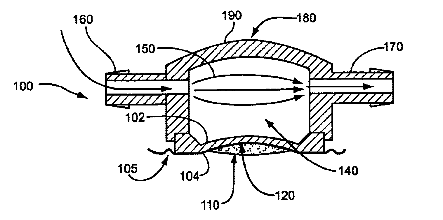
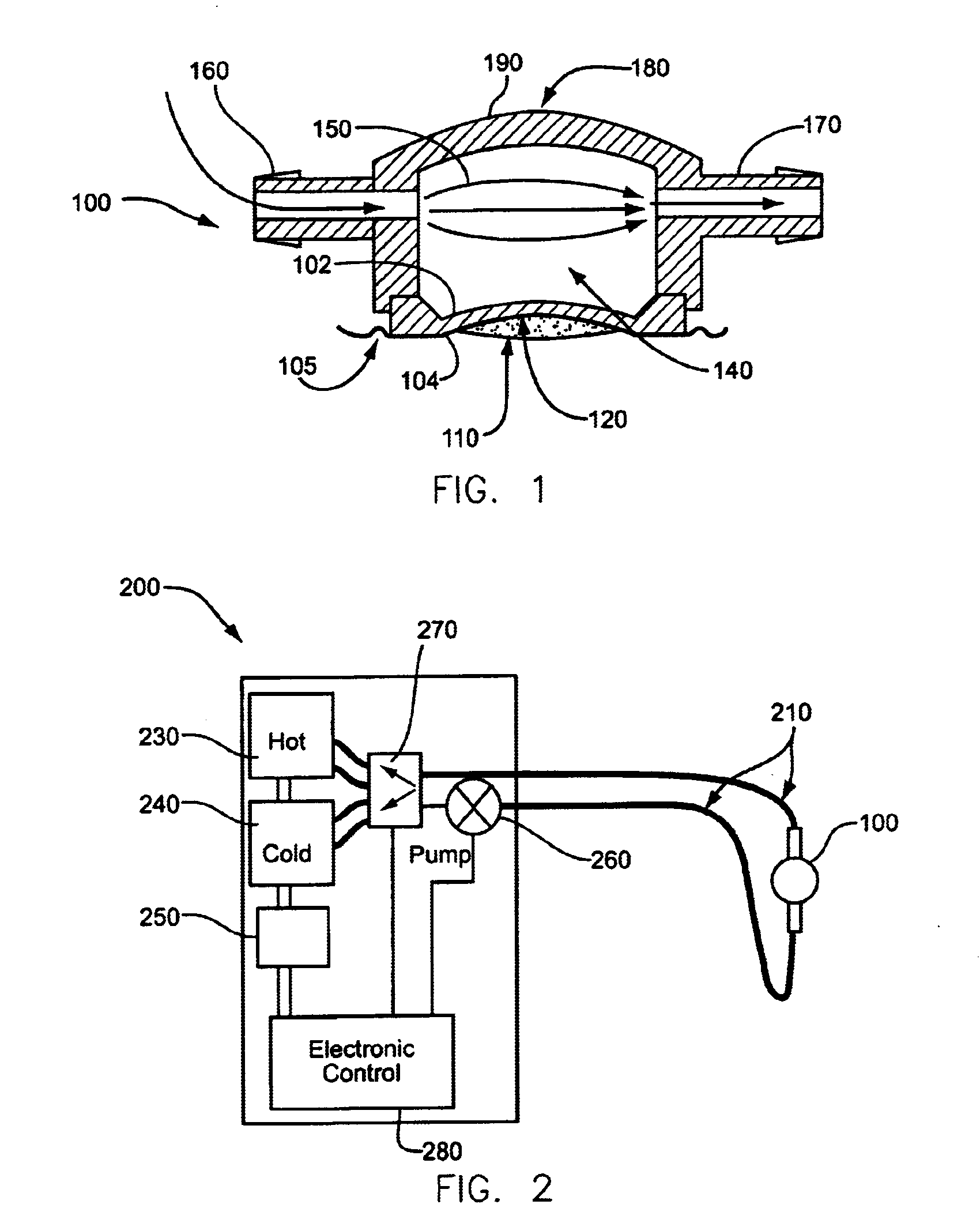
To form a modulator with the help of the mold, when the patient observes a light source, a mark is made on the cornea at the point behind which the reflection of the light source can be seen. The mold includes a membrane from polyethylene on the concave molding surface. The membrane includes a coated quantity of thermoreversible fluorescent hydrogel in a rigid form. Water of a high temperature is circulated inside the cavity of the mold for several minutes and the coated rigid hydrogel is liquefied.

Thereafter, water of a temperature of about 45.degree. C. continues circulating in the cavity of the mold to keep the hydrogel in liquid form until the time of application. While the patient observes the light source through the mold, the mold is placed centrally with the help of the mark that the mold bears on its convex surface. Also, the mold is rotated so that the image of the light source that is formed from the convex surface of the mold coincides with the m...

example 3

MATERIALIZATION EXAMPLE 3

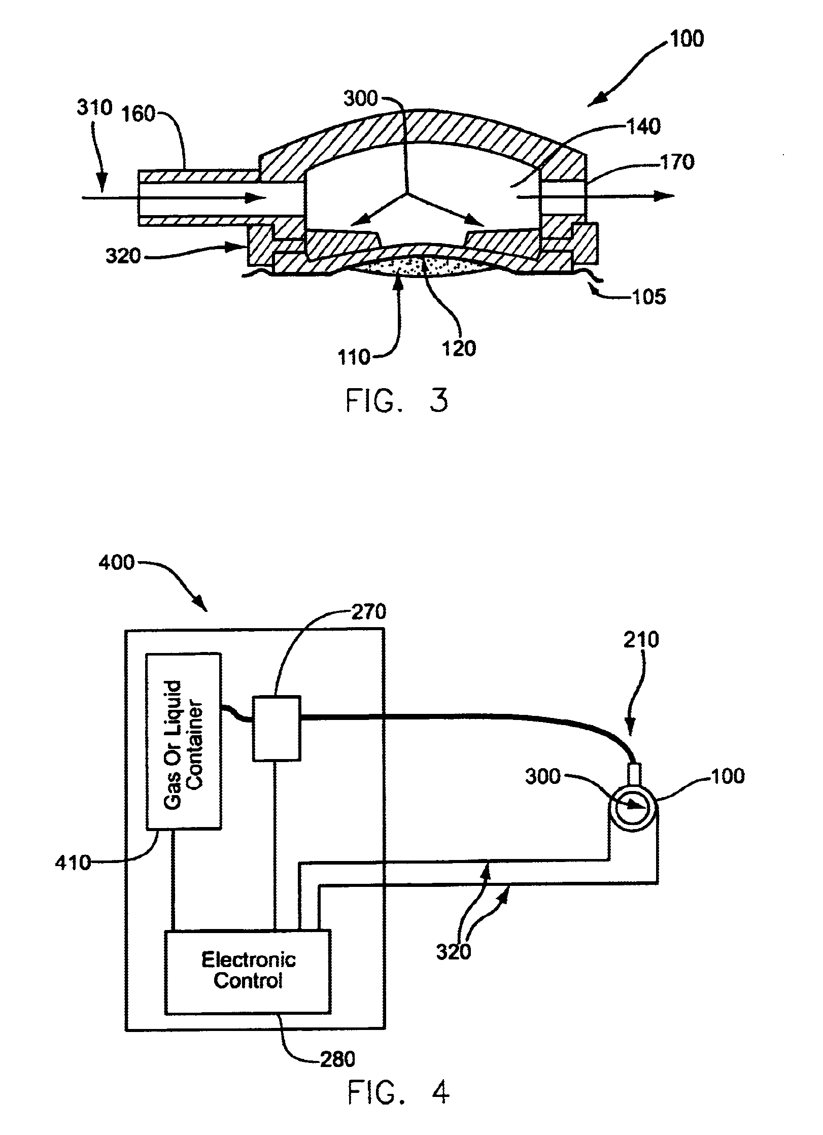
The cavity of the molding lens 100 includes heating elements 300, 500, e.g. electric resistive elements. On the external surface of the mold there are junctions through which the electric current enters the heating elements 300, 500. The mold is heated up when electric current is switched on. To cool the molding lens 100 and substance located on the molding lens, such as hydrogel, a low temperature liquid or gas, for example liquid nitrogen or CO.sub.2, may be inserted through this socket in the cavity.

To form the modulator with the help of this mold, when the patient observes a light source, a mark is made on the cornea at the point behind which the reflection of the light source can be seen. The mold includes a membrane of polyethylene located on the concave molding surface. On the membrane there is coated a quantity of thermoreversible fluorescent hydrogel in rigid form. A current is supplied in the heating elements 300, 500 in the mold for a time needed ...


PUM

PropertyMeasurementUnit
temperatureaaaaaaaaaa
diameteraaaaaaaaaa

Abstract

A device for helping to correct imperfections of a cornea includes a molding lens. The molding lens includes an external surface having a concave shape to correspond to the desired shape of the cornea. Heating and cooling elements are located with the molding lens to control the temperature the molding lens, and thus to control the temperature of a substance located on the molding lens.

Description

Different types of known modulators for shaping the cornea of an eye have been proposed for refractive surgery. Widely used is a modulator from photoabltable polymer that is placed in the optical path of a transportation system of a laser beam. This type of modulator, which has the shape of a spherical or of a toroidal lens is used for the correction of the usual refractive irregularities, like myopia or astigmatism. A modulator remote from the eye has the disadvantage, however, of correcting only simple and predefined refractive irregularities of the eye.It is also known to cover of the corneal surface, just before irradiation, with a solution of collagen which solidifies immediatelly after its placement over the cornea. The collagen typically covers the irregularities of the corneal surface. The collagen through the surface forms a relatively smooth external surface. This smooth surface is "projected" finally on the cornea due to the same ablation rate of collagen and the cornea. ...

Claims


Application Information

Patent Timeline
Patent Type & Authority Patents(United States)
IPC IPC(8): A61F9/01A61F9/007A61F9/008
CPCA61F9/008A61F9/00819A61F9/00804A61F2009/00872
Inventor PALLIKARIS, IOANNISGINIS, HARILAOS
Owner PALLIKARIS IOANNIS
Why Eureka
Try Eureka