Handheld laser system emitting visible and non-visible radiation

a laser system and laser beam technology, applied in the field of handheld laser systems emitting visible and non-visible radiation, can solve the problems of difficulty in directing the beam at the proper location on the target, lack of guidance as to whether the correct energy density has been delivered to the target, and insufficient method

Inactive Publication Date: 2004-04-20
FOSTER-MILLER
View PDF8 Cites 48 Cited by
  • Summary
  • Abstract
  • Description
  • Claims
  • Application Information

AI Technical Summary

Benefits of technology

The present invention will be further described through the use of three examples. The first example is a detailed description of a hand-held implementation of the preferred embodiment of the invention. The second example describes the use of the apparatus of the first example for laser tissue soldering. The third example illustrates an advantage of the present invention over the prior art.
The following examples are provided as representative implementations and uses of the present invention, but are not meant to limit or restrict the scope of the invention claimed herein. For example, the apparatus described in

Problems solved by technology

When the lasers operate at wavelengths which are not readily visible, e.g., near-infrared, infrared, or ultraviolet wavelengths, or when a laser beam which emits visible radiation is pulsed so that it might not be emitting when the operator is aiming the laser beam, it is difficult for an operator to direct the beam at the proper location on the target.
However, that method is often not satisfactory because it does not identify the complete area that is covered by the laser beam, and because it requires a mixing of the optical sources, such that the visible beam and the nonvisible beam are traveling along the same optical path.
Furthermore, that method provides no guidance as to whether the correct energy density has been delivered to the target.
However, infrared and near-infrared lasers such as the CO.sub.2 and Nd:YAG lasers (as well as the 810 nm diode laser mentioned above) are not visible to the naked eye.
However, this system does not define the incident area of the nonvisible beam, or provide any method for determining whether the correct power density and energy density is being delivered to the target.

Method used


Image

  • Handheld laser system emitting visible and non-visible radiation
  • Handheld laser system emitting visible and non-visible radiation
  • Handheld laser system emitting visible and non-visible radiation

Examples


example 1

The primary components of the hand-held implementation of the present invention described in this Example are shown schematically in FIG. 5. The apparatus consists of laser diode 51, visible light sources 52, a fan-cooled finned heat sink 57, optical fibers 53 transmitting the visible light beam (nine optical fibers were actually used), optical fiber 54 transmitting the nonvisible laser beam, optical fiber connector 58 which holds optical fibers 53 and 54 in optical contact with fiber collimating lens 56, a power supply such as NiCd or Li-ion batteries 55, laser activation switch 41, manual shutter 42, display / control panel 44 and laser housing 45. Optical fiber connector 58 centers optical fiber 54 in the middle of optical fibers 53, such that the visible beams emitted from the ends of optical fibers 53 define the position of nonvisible beam 43 emitted from the end of optical fiber 54 and transmitted by collimating lens 56.

Laser diode 51 is a High Power Devices Model No. HPD1020-BU...

example 2

The apparatus described in Example 1 can be used as follows to perform the LTS procedure. An albumin-based protein solder preparation can be used as described in U.S. Pat. Nos. 5,209,776 and 5,292,362, which are incorporated by reference herein. Briefly, a pasteurized 25% human albumin solution (The New York Blood Center, Melville Biologics Division, New York, N.Y.) is lyophilized. (dehydrated) under sterile conditions to powder form (2.5 g albumin) and reconstituted in 6.0 ml sterile water (42% albumin solution). After sterile filtration through a 0.2 m pore-sized filter, 200 .mu.l aliquots of this solution are mixed with 100 .mu.l of sterile ICG dye (CardioGreen, 2.5 mg / ml, Becton-Dickinson, Cockeyville, MD) and stored at -20.degree. C. Twenty-four hours prior to use, 1 to 2 aliquots are thawed and combined with 200 .mu.l of sodium hyaluronate (Healon, 10 mg / ml, Kabi Pharmacia Ophthalmics, Monrovia, Calf.) to make a total volume of 0.5 ml / aliquot. The final solution is vortexed fo...

example 3

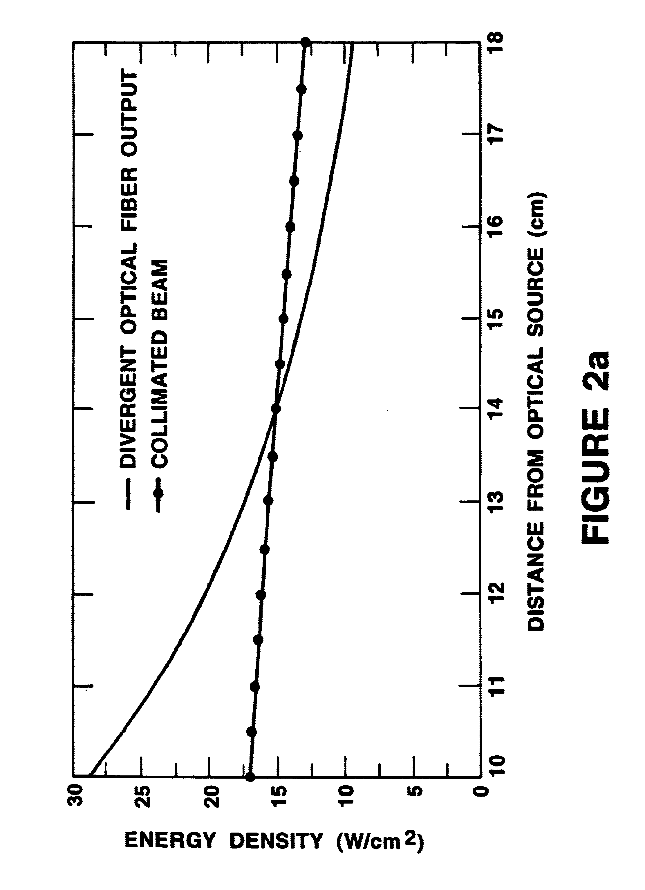
To quantify how much of an improvement the collimated beam provides, a laboratory experiment was performed first with the original bare fiber delivery system, and then with the collimated fiber system. Each delivery fiber was moved slowly by hand over a simulated wound for a period of two minutes. The fluctuation in power density was monitored and the comparison is plotted as shown in FIG. 8. As evident from FIG. 8, the collimated fiber system has eliminated the dependence of power density on distance from the target (as also demonstrated by FIGS. 2a to 2c). These results demonstrate convincingly that the collimated beam is a much safer and more effective method for delivering beam power.

It is anticipated that alterations within the purview of one of ordinary skill in the art will be made to the above described preferred embodiment based on technology advances, for example, in the areas of laser diodes, rechargeable batteries, microelectronics, and such changes do not affect the sco...


PUM


Abstract

A laser system for use in medical, industrial, commercial or research applications in which the location and energy and power density of a nonvisible (e.g., infrared or ultraviolet) laser beam is defined by a plurality of visible beams. Collimating optics are used to direct both the nonvisible and visible beams on the target, such that when the visible beam is in focus on the target, the nonvisible beam has the optimum energy and power density. One implementation of the invention is a self-contained hand-held surgical laser that provides surgeons with the optimal laser beam parameters for laser tissue soldering.

Description

This invention relates to manually-directed lasers that emit beams that are not readily visible to the naked eye, such as lasers used for medical applications (e.g., laser tissue soldering), and lasers used in industrial, commercial or research applications.Manually-directed lasers are used in medical and in industrial applications to direct energy at a target. When the lasers operate at wavelengths which are not readily visible, e.g., near-infrared, infrared, or ultraviolet wavelengths, or when a laser beam which emits visible radiation is pulsed so that it might not be emitting when the operator is aiming the laser beam, it is difficult for an operator to direct the beam at the proper location on the target. One method for resolving this problem is to use a visible beam that is collinear with the non-visible beam. However, that method is often not satisfactory because it does not identify the complete area that is covered by the laser beam, and because it requires a mixing of the ...

Claims


Application Information

Patent Timeline
Patent Type & Authority Patents(United States)
IPC IPC(8): A61B18/20A61B18/22G02B6/42A61B17/00
CPCA61B17/00491A61B18/22G02B6/4206A61B2017/00517A61B2018/2025A61B2017/00477A61B2018/00172A61B2018/202A61B2018/2211
Inventor GERMAN, JOHN D.SAGGESE, STEVEN J.TOCCI, MICHAEL D.
Owner FOSTER-MILLER
Why Eureka
Try Eureka