
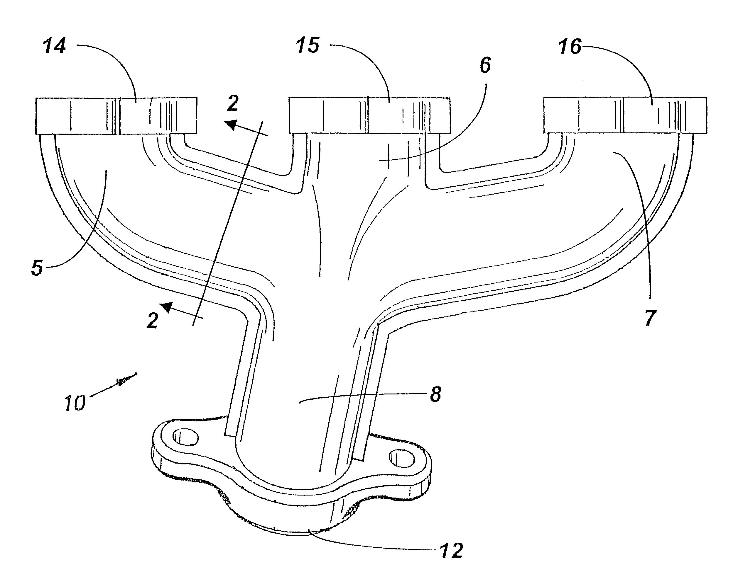
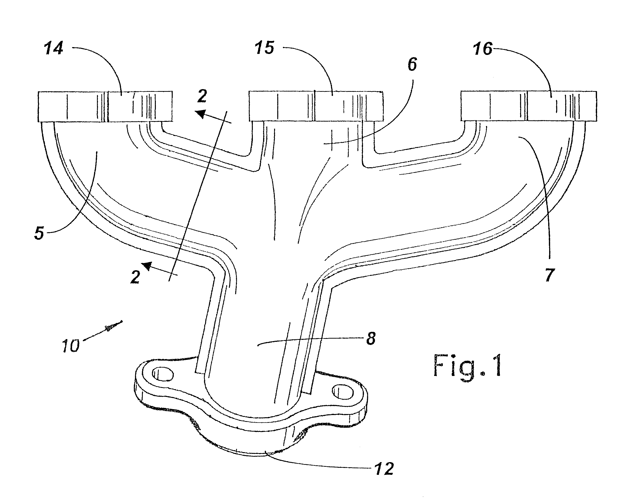
Insulated exhaust manifold

a technology of exhaust manifolds and exhaust pipes, applied in the direction of machine/engine, sound absorption, surface coverings, etc., can solve the problems of unreasonably complex exhaust manifold manufacturing, less mass of welded tubing exhaust manifolds, and loss of thermal energy,

Inactive Publication Date: 2004-04-27
INTPROP HLDG
View PDF56 Cites 39 Cited by
  • Summary
  • Abstract
  • Description
  • Claims
  • Application Information

AI Technical Summary

Benefits of technology

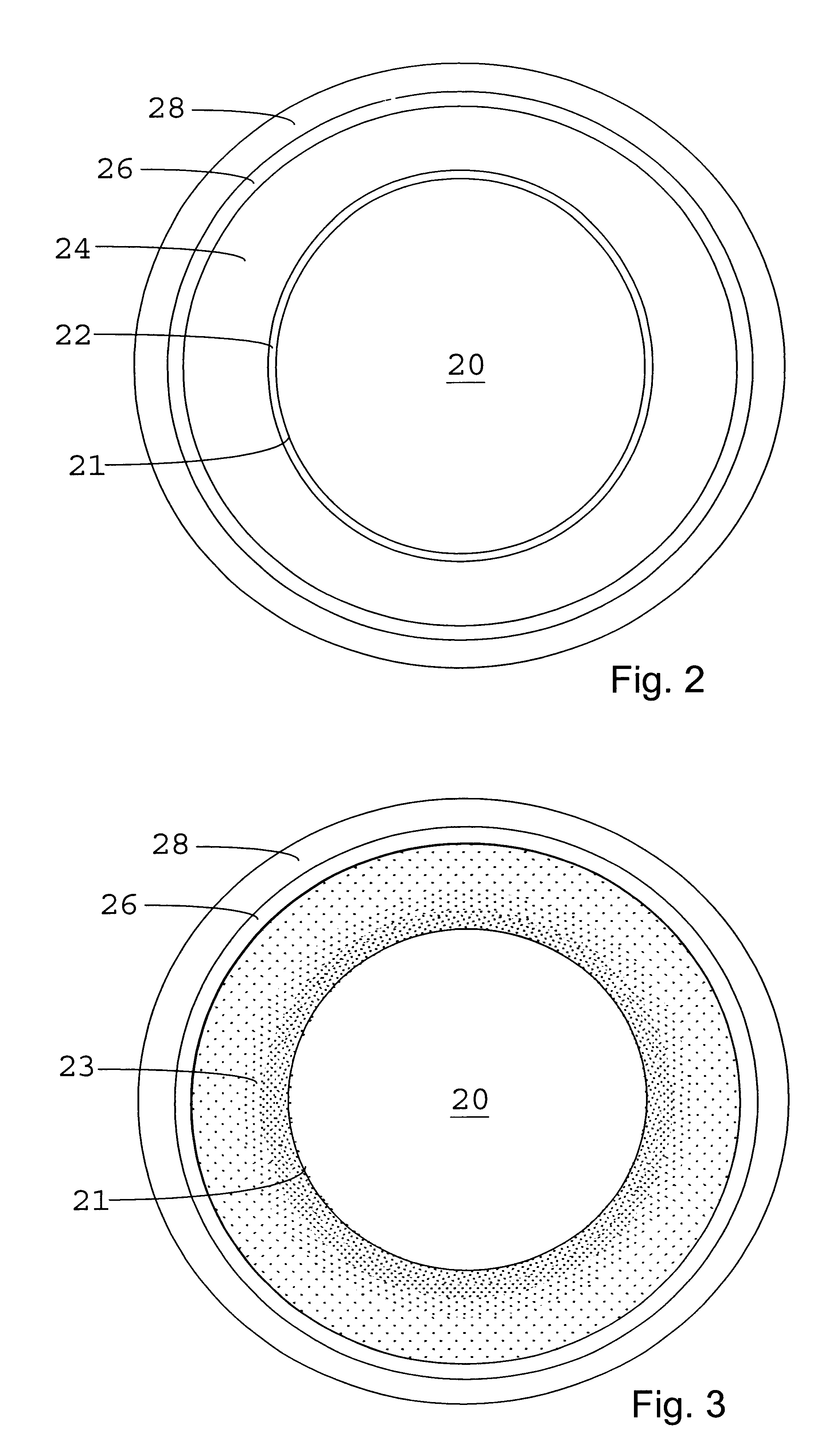
"The present invention relates to an insulated exhaust manifold for internal combustion engines in motor vehicles. The invention aims to speed up the light off of the catalytic converter by minimizing the time it takes for the exhaust gas to reach the converter. The invention provides an improved exhaust manifold that reduces the amount of heat conducted or convected away from the exhaust gas, resulting in higher temperature exhaust gas and faster light off. The insulation layer is made of ceramic fibers and ceramic filler material, and the outer structural layer is made of metal. The method of making the insulation layer involves vacuum forming the layer and then casting a metal outer layer over it. The invention helps to minimize harmful pollutants emitted from the engine and provides a more efficient and effective exhaust system."

Problems solved by technology

Unfortunately, the catalytic converter is normally mounted downstream of the exhaust manifold which conducts the heated exhaust gas from the engine.
This loss in thermal energy reduces the exhaust gas temperature before it reaches the catalytic converter and delays light off.
Cast iron exhaust manifolds are useful but heavy.
Welded tubing exhaust manifolds have less mass, but are complicated and expensive.
Double-walled welded tubing exhaust manifolds have been suggested, with an air gap between the walls, but the two walls have the same thickness and are both structural and such an exhaust manifold would be unreasonably complex to manufacture.
In addition, the metal inner layer is subject to erosion or loss of integrity over time from thermal cycling.

Method used


Image

  • Insulated exhaust manifold
  • Insulated exhaust manifold
  • Insulated exhaust manifold

Examples


Embodiment Construction

In the description that follows, when a range such as 5 to 25 (or 5-25) is given, this means preferably at least 5 and, separately and independently, preferably not more than 25. As used herein, the porosity of a layer or material is the ratio of void volume to total volume of that layer or material. For example, a layer having a porosity of 30% has a void volume equal to 30% of the layer's total volume. Localized porosity refers to the local porosity of a layer at a given radial distance from that layer's inner surface. Unless otherwise explicitly stated, localized porosities are uniform for a given radial distance from the inner surface of a particular layer. The notation "wt. %" means percent by weight.

The term ceramic includes any inorganic compound, typically (though not necessary) crystalline, formed between a metallic (or semimetallic) and a nonmetallic element, and mixtures thereof; for example, alumina (Al.sub.2 O.sub.3), titania (TiO.sub.2), and boron nitride (BN), where A...


PUM

PropertyMeasurementUnit
thickaaaaaaaaaa
thickaaaaaaaaaa
thickaaaaaaaaaa

Abstract

An exhaust manifold is provided having substantially ceramic inner and insulation layers. The manifold preferably has a metal outer structural layer to impart strength to the manifold. The ceramic layers are made of ceramic fibers with the interstitial spaces between the fibers being filled with ceramic filler material. The preferred ceramic fibers are aluminosilicate fibers. The preferred ceramic filler material is alumina, silica, glass-ceramic or other metal oxide. A method of making an exhaust manifold having a substantially ceramic inner and insulation layer is also provided.

Description

1. Field of the InventionThe present invention relates to an exhaust manifold, and more particularly to an insulated exhaust manifold for an internal combustion engine in a motor vehicle.2. Description of Related ArtCatalytic converters in motorized vehicles, particularly passenger automobiles, must reach a certain temperature before they "light off". Light off occurs when the catalytic converter begins to convert harmful pollutants by oxidizing carbon monoxide and hydrocarbons to CO.sub.2, and reducing NO.sub.x to N.sub.2 and O.sub.2. It is important to minimize the time to light off once a car is started to minimize the amount of harmful pollutants emitted to the atmosphere.Catalytic converters are typically heated to light off by the high temperature engine exhaust gas itself. Unfortunately, the catalytic converter is normally mounted downstream of the exhaust manifold which conducts the heated exhaust gas from the engine. A typical exhaust manifold is made of metal, or substanti...

Claims


Application Information

Patent Timeline
Patent Type & Authority Patents(United States)
IPC IPC(8): B01D53/94C04B35/80C03C14/00F01N3/28F01N7/10F01N7/16F01N7/00F01N7/18F01N13/10F01N13/16F01N13/18
CPCB01D53/945C03C14/002C04B35/10C04B35/565C04B35/803C04B35/806F01N3/2853F01N3/2864F01N13/102F01N13/16F01N13/1888B01D53/9454Y10T428/24132C03C2214/02C03C2214/30C04B2235/3418C04B2235/5224C04B2235/5228C04B2235/5232C04B2235/5236F01N2260/10F01N2310/00F01N2310/06F01N2330/06F01N2510/00F01N2510/02F01N2510/06F01N2530/06F01N2530/26Y02T10/22C04B35/80Y02T10/12
Inventor MOORE, III, DAN T.SANE, AJIT Y.
Owner INTPROP HLDG
Learn More