Method and apparatus for filling or refilling a needle-less injector

a needle-less injector and needle-less technology, which is applied in the direction of liquid handling, packaged goods, food processing, etc., can solve the problems of increasing the danger of contamination exposure of needle injectors, severely hampering the ability of those in need of regular injections to receive convenient, and the burden on the diabetic population is larg

Inactive Publication Date: 2004-06-29
PENJET CORP
View PDF187 Cites 56 Cited by
  • Summary
  • Abstract
  • Description
  • Claims
  • Application Information

AI Technical Summary

Benefits of technology

In an alternate embodiment, a product may be initially contained in a storage vial. As above, the product may be a latent fluid, a lyophilized solid, a non-lyophilized solid, or any other suitable product. The storage vial may be adapted to mate with the injector end of a coupling device, such that the coupling device may be utilized to provide fluid communication between the storage vial and a vessel. In this configuration, a fluid may be drawn out of the storage vial and into a vessel. The fluid may thereafter be filled into a needle-less injector by removing the storage vial and mating the coupling device to a needle-less injector. Or, in an alternate embodiment, a product may be contained in the storage vial, and fluid contained in a vessel may be introduced into the storage vial wherein the fluid and the product may mix to form a mixture. The mixture may be subsequently drawn out of the storage vial and into the vessel. The mixture may thereafter be filled into a needle-less injector by removing the storage vial and mating the coupling device to a needle-less injector. This latter embodiment may be advantageous for the storage and mixing of lyophilized products, or various products that do not have a long shelf life when stored in solution.
In one embodiment of the present invention, the storage vial 1200 may contain a product 1201, and the vessel 103 may contain a fluid 104 (FIG. 12a). Fluid 104 may be transferred from the vessel 103 to the storage vial 1200 through the coupling device 101 (FIG. 12b). The fluid 104 and the product 1201 may mix in the storage vial 1200 to form a mixture 1202. It may be advantageous to further mix the fluid 104 and product 1202 by agitating the two components in the storage vial 1200 such as by shaking the assembly. The storage vial 1200 may then be oriented above the coupling device 101 (FIG. 12c) and the mixture 1202 may be drawn out of the storage vial 1200 (FIG. 12d). Notably, the storage vial 1200 need not be oriented above the vessel 103 to withdraw a fluid or mixture therefrom; however, this may avoid the transfer of air contained in the storage vial into the vessel 103. The storage vial 1200 may then be removed from the coupling device 101, and a needle-less injector 102 may then be filled with the mixture 1202 in accordance with any of the embodiment discussed herein.

Problems solved by technology

Needle injectors suffer from increased danger of contamination exposure to health care workers administering injections, and to the general public when such injectors are not properly disposed of In fact, safety considerations surrounding needle injectors are of such paramount concern that they are prohibited from some locations.
This may severely hamper the ability of those in need of regular injections to receive convenient and timely medical attention.
One heavily burdened population is diabetic children who require insulin injections, since children are not permitted to bring needle injectors to some school campuses.
Filling such a device a substantial amount of time prior to use presents a variety of concerns, not the least of which is the risk of bacterial contamination on the exterior of such a device owing to fluid remaining on the exterior thereof after the filling operation is completed.
Additionally, as some ailments require periodic injection of varying amounts of a medication, it may be impractical for a user to employ a pre-filled needle-less injector.
By design, a pre-filled injector already contains a particular amount of a medication, and in the case of an injection whose requisite volume cannot be determined in advance, one can not assume that the volume of a pre-filled injector will be suitable.
Also, if multiple injections are to be administered throughout the day, one may not wish to carry several pre-filled injectors, as this may be cumbersome and inconvenient.

Method used


Image

  • Method and apparatus for filling or refilling a needle-less injector
  • Method and apparatus for filling or refilling a needle-less injector
  • Method and apparatus for filling or refilling a needle-less injector

Examples


example 2

Filling a Needle-Less Injector Using a Filling Device

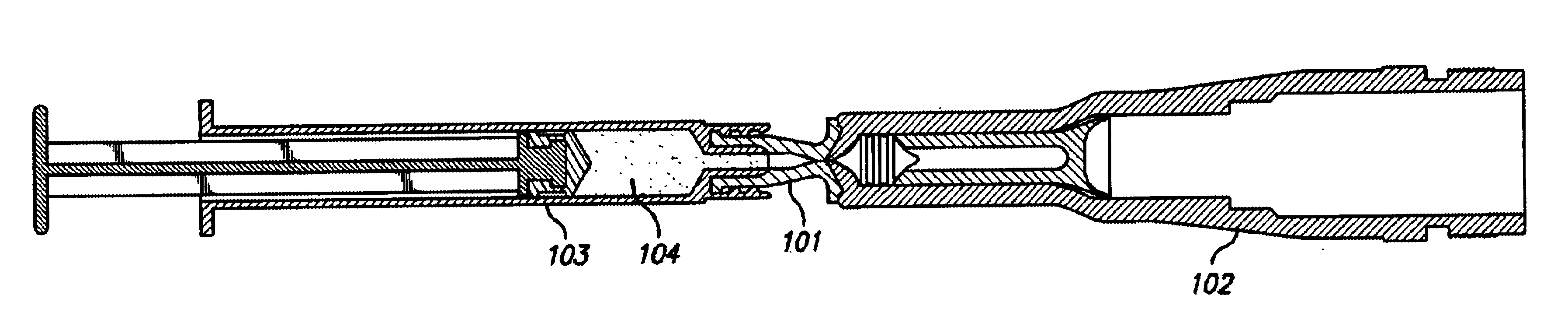
A filling device includes both a vessel and a coupling device. The filling device is mated to a needle-less injector by holding the injector end of the coupling device against the receiving surface on a dispensing end of a needle-less injector. The vessel included in the filling device is a syringe, affixed to the coupling device with a snap fitting. The needle-less injector contains a lyophilized solid medication prior to filling via the coupling device, and the filling device contains a diluent.

The plunger of the filling device is depressed, forcing the diluent through the coupling device, through corresponding orifices disposed on the coupling device and needle-less injector, and into the needle-less injector. Graduations on the Luer syringe provide a user with a visual cue to determine when the desirable amount of diluent has been introduced into the injector. Upon filling the needle-less injector with the desirable amount of ...

example 3

Filling a Needle-Less Injector Using Filling Equipment

Filling equipment includes a reservoir of a pharmaceutical fluid and a series of tubes, each of which terminates with an adapter. A vessel end of a coupling device is connected to each of the adapters. A series of needle-less injectors is mated to the series of coupling devices, and an amount of the pharmaceutical fluid is filled into each needle-less injector.

After each of the needle-less injectors is filled with an amount of the pharmaceutical fluid, the coupling devices are removed from the needle-less injectors and another series of needle-less injectors is mated to the same coupling devices. An amount of the pharmaceutical fluid is then filled into each of this second series of needle-less injectors.

After each of the second series of needle-less injectors has been filled with an amount of the pharmaceutical fluid, the coupling devices are removed from the needle-less injectors, and a rubber cap is placed on each.

example 4

Preparing a Vessel for Filling a Needle-Less Injector with a Fluid Using a Coupling Device and a Storage Vial

A Luer syringe is affixed to the vessel end of a coupling device, by screwing the, elements together (i.e., two elevated tabs on the vessel end of the coupling device cooperate with interior screw threading on the Luer syringe). The cap is removed from a storage vial, and the storage vial is attached to the injector end of the coupling device, also by screwing the elements together (i.e., exterior screw threading disposed upon the storage vial cooperates with interior screw threading configured upon an attachment mechanism). The storage vial contains a fluid.

The storage vial is oriented above the Luer syringe to minimize transfer of air therefrom. The plunger of the Luer syringe is then pulled back, withdrawing the fluid out of the storage vial through corresponding orifices disposed on the storage vial and coupling device, through a channel in the coupling device, through a ...


PUM

PropertyMeasurementUnit
speedaaaaaaaaaa
speedaaaaaaaaaa
speedaaaaaaaaaa

Abstract

Devices and methods are described for filling or refilling a needle-less injector. A coupling device is attached to a vessel, and mated to the dispensing end of a needle-less injector. A volume of fluid may be transferred via the coupling device, from the vessel to the injector. Air may be removed from the injector prior to the injector, vessel, and coupling device being separated from one another. In alternate embodiments, the vessel may include filling equipment capable of filling or refilling multiple needle-less injectors simultaneously, in series, or both. In other embodiments, a coupling device may be used to withdraw a fluid from a storage vial into a vessel for filling a needle-less injector. A storage vial may alternately contain a product, and a fluid may be introduced therein via a coupling device to create a mixture, which may be subsequently withdrawn into a vessel for filling a needle-less injector.

Description

This invention relates to the filling of needle-less injectors, and, in particular embodiments, to devices and methods for filling or refilling modular gas-pressured needle-less injectors.Traditionally, fluids such as medications are injected into patients, either subdermally or intradermally, using hypodermic syringe needles. The body of the syringe is filled with the injectable fluid and, once the needle has pierced the patient's skin, the syringe plunger is depressed so as to expel the injectable fluid out of an opening in the needle. The person performing the injection is often a trained medical services provider, who manually inserts the hypodermic needle between the layers of a patient's skin for an intradermal injection, or beneath the skin layers for a subcutaneous injection. However, injections are also routinely performed by laypersons, as in the case of diabetics self-administering insulin injections.Needle injectors suffer from increased danger of contamination exposure ...

Claims


Application Information

Patent Timeline
Patent Type & Authority Patents(United States)
IPC IPC(8): A61J1/00A61M5/30A61J1/20
CPCA61J1/2089A61J1/2096A61J2001/2044A61M5/30A61J1/2044
Inventor CASTELLANO, THOMAS P.WISE, ROGER R.LEVY, SETH D.
Owner PENJET CORP
Why Eureka
Try Eureka