Self-priming dialysis filter

a filter and dialysis technology, applied in the direction of filtering separation, moving filter element filter, separation process, etc., can solve the problems of increased risk of peritonitis, poor transfer technique, peritoneal access, etc., to reduce the risk of peritonitis, increase the clearance of toxins, and reduce the effect of unprotected connections

Inactive Publication Date: 2004-07-06
BAXTER INT INC +1
View PDF8 Cites 12 Cited by
  • Summary
  • Abstract
  • Description
  • Claims
  • Application Information

AI Technical Summary

Benefits of technology

A novel filter of this invention uses an absolute membrane micro-filter to screen out all bacteria and virtually all the organic matter. Currently, commercially available 0.2 micron absolute membrane filters are considered to be satisfactory, but it is recognized that other sizes and types of filter media will also be operable for the practice of this invention. In practice, the filter may be attached to an implanted catheter for an interval encompassing several transfers, using aseptic technique. It is generally convenient and sufficient to change filters once per day. Once the filter has been put in place, the patient is free to transfer solution virtually anywhere and in any situation. The filter provides a barrier between the environment and the perito

Problems solved by technology

There are several problems associated with using CAPD to treat ESRD.
The main drawback is the increased risk of peritonitis.
According to the USRDS some of the causes of peritonitis in CAPD patients are poor transfer technique, peritoneal access, less overall clearance of small uremic toxins, and possible deleterious effects of the dialysis fluid on the macrophage function.
A second problem associate with current CAPD procedures is the introduction of air into the peritoneal ca

Method used


Image

  • Self-priming dialysis filter
  • Self-priming dialysis filter
  • Self-priming dialysis filter

Examples


Embodiment Construction

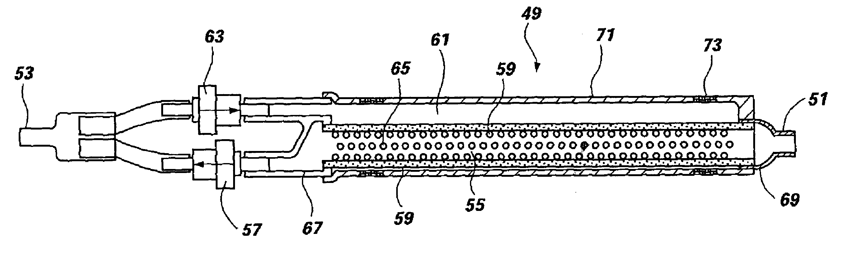
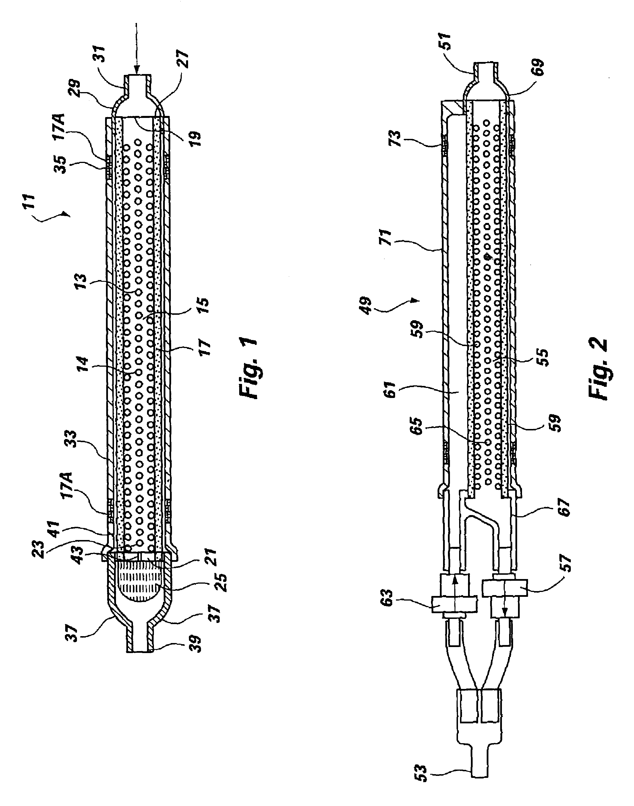
FIG. 1 illustrates a filter, generally 11 ,of this invention, which includes a tube 13 that has multiple perforations 14 in a middle portion 15, being constructed of resilient material having physical properties selected to ensure that the tube 13 will retain its shape under a small stress and if deformed under a higher stress, will return to approximately its original shape once the stress has been removed. Filter material 17 is wrapped around the perforated tube 13 in a sealed relationship, such that all of the holes 14 in the perforated portion 15 are covered by a membrane of filter material 17. The filter material is hydrophilic, and allows the flow of liquid but constitutes a barrier against the flow of air. The holes 14 in the tube 13 are positioned within the region 15 between boundaries 19, 21 defined by circumferential sealed interfaces between the filter membrane 17 and the exterior surface of the tube 13. One end 23 of the perforated tube 13 is provided with a check valve...


PUM

PropertyMeasurementUnit
Pore sizeaaaaaaaaaa
Flow rateaaaaaaaaaa
Volumeaaaaaaaaaa

Abstract

A medical filter (11) is constructed as a container with an interior volume in open fluid communication with a patient connection element (31) and a transport connection element (39). Filter support structure (13) mounted within the interior is structured as a thin, perforated member (14) carrying hydrophilic filter medium (17). A first flow path directs spent dialysate from the patient across the surface of the filter medium (17) to the transport connection (39). A second flow path directs fresh dialyalysate from the transport connection (39) through the filter medium (17) and the perforated support structure (13) to the patient connection (31).

Description

This invention relates to kidney dialysis, and provides an improved filter system for home use dialysis procedures.When a person's kidney function is about three percent (3%) of normal, the person is said to have end stage renal disease (ESRD). Continuous ambulatory peritoneal dialysis (CAPD) is a medical therapy used to remove the toxins that accumulate in the blood when the kidneys stop functioning. Peritoneal dialysis uses the person's peritoneal lining as a filter mechanism. The patient introduces dialysis solution into the peritoneal cavity through a surgically implanted catheter. To accomplish this form of dialysis, the patient leaves the solution in his or her peritoneal cavity for about 4 hours and then drains the solution out of the peritoneal cavity. During the time the dialysis solution is in the patient's peritoneum, the toxins in the patients blood streem diffuse through the peritoneal lining into the dialysis solution. When the solution is drained, the toxins are flush...

Claims


Application Information

Patent Timeline
IPC IPC(8): B01D63/08B01D63/06B01D29/11B01D29/00A61M1/16A61M1/22A61M1/28A61M1/36B01D29/13B01D61/18B01D61/20B01D61/28B01D65/00B01D71/68
CPCB01D61/18B01D61/20B01D63/06B01D63/08B01D63/082B01D65/00A61M1/288A61M1/16A61M1/3643A61M1/3644A61M2205/75
Inventor HAIGHT, LEVOY G.
Owner BAXTER INT INC
Why Eureka
Try Eureka