Birefringence compensated integrated optical switching or modulation device

a planar waveguide and integrated technology, applied in the direction of optical waveguide light guide, instruments, optics, etc., can solve the problems of non-linear increase in pdl and polarization dependent loss, and achieve the effect of reducing the width of the heated arm, and reducing the pdl

Inactive Publication Date: 2004-07-06
LUMENTUM OPERATIONS LLC
View PDF6 Cites 24 Cited by
  • Summary
  • Abstract
  • Description
  • Claims
  • Application Information

AI Technical Summary

Benefits of technology

Accordingly, a preferred embodiment of the invention would provide the desired normally on characteristic but without the PDL caused by the thermally induced birefringence. In one aspect of the invention this result is achieved by inducing a slight birefringence in one of the arms. This embodiment can completely eliminate the PDL caused by the constant birefringence, as well as substantially improve device performance where the variable birefringence is predominant at high attenuation levels. Ideally the variable birefringence will be compensated completely such that the TE and TM polarization states are either in phase in both arm segments or out of phase, when the heater is energized to the high attenuation state.
A simple method of modifying the birefringence of one or more of the channel waveguide arms of the inventive device is to change the aspect ratio of the waveguide cross-section, as this can be easily implemented at the design stage using existing fabrication technology with known tolerances.
In order to compensate for the variable heating induced birefringence by waveguide geometry, the sign of the variable birefringence must be known. Consistent with experimental data and also stress models, applying heat to silica waveguides on silicon substrate induces negative birefringence, making the TM index higher than the TE one, as more stress is applied to the waveguide core in the direction parallel to the substrate than in the direction perpendicular to it. This birefringence can be compensated by geometry in two ways: by reducing the width of the heated arm or by increasing the width of the non-heated arm. In the more preferred embodiment the width of the non-heated arm is increased such that the variable and compensating birefringence effects are separated to prevent any coupling interaction that might compromise the predicted device performance.
In another preferred embodiment the compensating birefringence is achieved by decreasing the waveguide width where the heated arm is narrowed, rather than the non-heated arm. The width cannot be decreased too much, as this decreases the confinement of light in the waveguide and can result in more propagation loss.
Alternatively, a non-zero phase difference between the two arms (when actuator is not powered or energized) can be introduced intentionally in order to reduce the amount of power that needs to be applied to switch or modulate the device. That is the phase difference need not be limited to zero or integer multiples of .pi. when the actuator is not operated. Preferably, heaters or other actuators are present on both arm segments for alternative operation in order to either switch optical signal between output ports, select between the minimum and maximum attenuation states, or provide a continuously variable level of attenuation.

Problems solved by technology

Moreover, it has been found that polarization dependent loss may increase dramatically as the incident optical signal is attenuated or switched, as even a linearly proportional increase in birefringence with refractive index of the channel waveguide material results in a non-linear increase in PDL.

Method used


Image

  • Birefringence compensated integrated optical switching or modulation device
  • Birefringence compensated integrated optical switching or modulation device
  • Birefringence compensated integrated optical switching or modulation device

Examples


Embodiment Construction

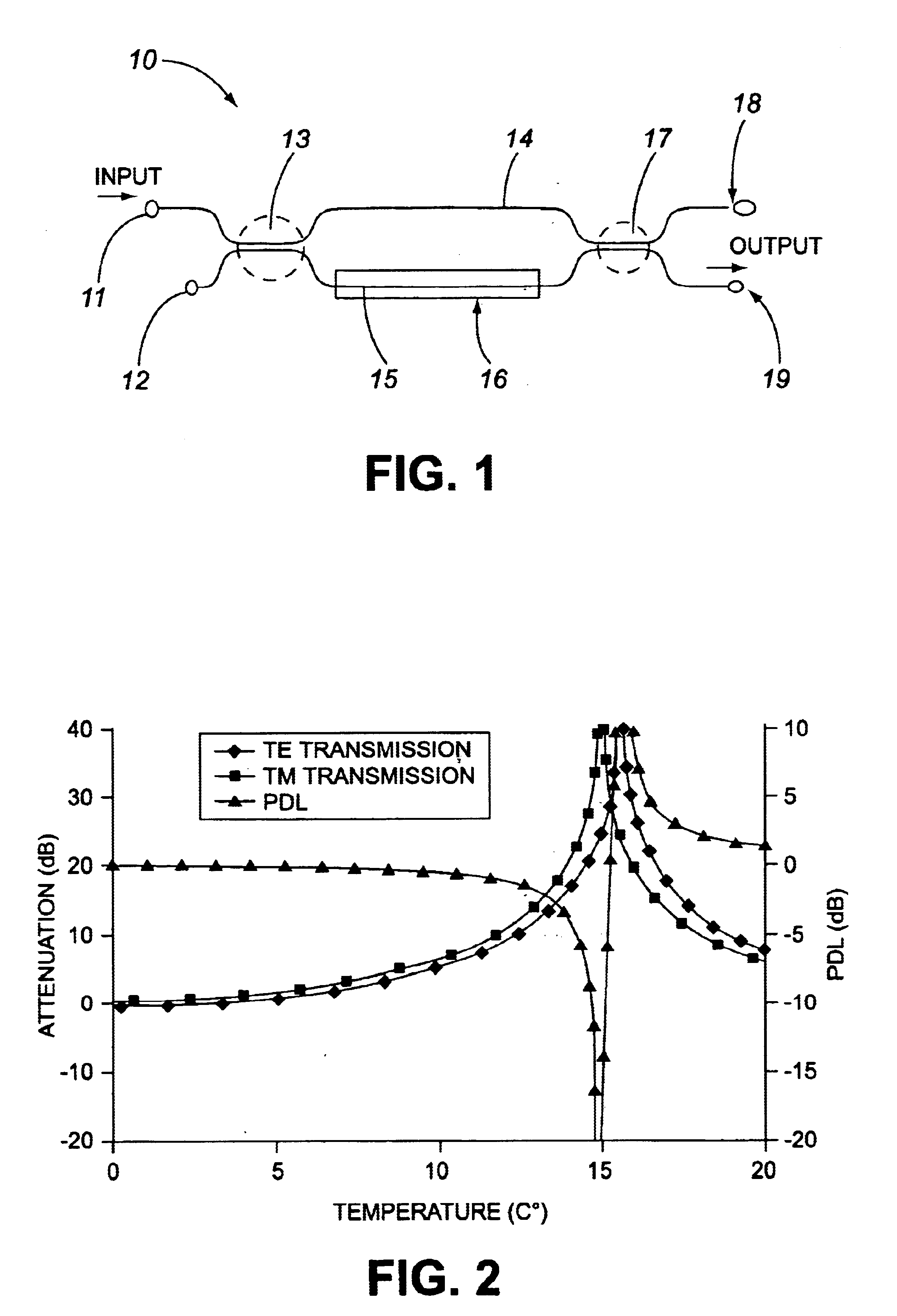
As a first example, one could compensate the 1.7.times.10.sup.-5 birefringence assumed in FIG. 2 by decreasing the waveguide width of the heated arm from 6 microns to 3.6 microns. This slight birefringence would again cause some PDL in the on state, but allow for very high contrast in the off state. FIG. 4 shows the calculated transmission of the two polarization states in such a compensated device. The two nulls overlap substantially, resulting in an increase in the maximum contrast ratio (for unpolarized light) from 20 dB to better than 30 dB. The PDL is less than 0.5 dB nearly everywhere, except for close to the nulls. It is important to note, as shown in FIG. 5, that even though the PDL has increased in the corrected device at zero bias, it is still lower than the uncorrected device nearly everywhere except for close to zero bias.

As a second example, one could compensate part of the birefringence assumed in FIG. 2 by increasing the waveguide width of the non-heated arm from 6 mi...


PUM

PropertyMeasurementUnit
widthaaaaaaaaaa
widthaaaaaaaaaa
widthaaaaaaaaaa

Abstract

A planar waveguide Mach-Zehnder interferometer (MZ) has improved performance as a variable optical attenuator as well as a thermo-optic switch (TOS) with reduced polarization dependent loss (PDL) in high attenuation states. The PDL was reduced by correcting for the increased birefringence that occurs on heating one waveguide arm by making the two waveguides inherently asymmetric, such that when one of the waveguides is heated, the differential birefringence of the two arms becomes zero. This asymmetry can be realized simply by changing the width of one of the waveguides. The modified device allows for very small PDL in the high attenuation state of a VOA and for theoretically perfect contrast in a TOS in the off state, with only a small penalty in PDL of the on state.

Description

BACKGROUND OF INVENTIONThe present invention relates to an integrated planar waveguide optical device suitable for switching optical signals between three or more ports and / or modulation of the optical intensity, and more particularly, to an integrated optical Mach-Zehnder interferometer device having low polarization dependent loss at a high level of attenuation or signal isolation.Integrated optical switching or modulation devices are based on the conventional Mach-Zehnder (M-Z) interferometer geometry and comprise two or more channel waveguides formed on a planar substrate. The two channel waveguides are usually parallel to each other and separated at the terminal ends, which form the input and output ports of the device. The waveguides come in sufficiently close proximity to each other in two discrete regions permitting exchange of light by optical coupling. These regions, referred to as optical couplers, generally divide the incident light beam arriving from an input port of on...

Claims


Application Information

Patent Timeline
Patent Type & Authority Patents(United States)
IPC IPC(8): G02F1/01G02F1/225
CPCG02F1/225G02F1/0147G02F2203/48
Inventor PEZESHKI, BARDIAMISSEY, MARKSALA, ANCA L.LIDDLE, CRAIG D.FONDEUR, BARTHELEMY
Owner LUMENTUM OPERATIONS LLC
Why Eureka
Try Eureka