Precision automatic gain control circuit

a gain control and precision technology, applied in the direction of gain control, volume compression/expansion having semiconductor devices, volume compression/expansion, etc., can solve the problems of limited input signal swing capability, agc stage unacceptable, and total harmonic distortion (thd) greater than 1%, so as to optimize both noise and linearity performance, the effect of low absolute gain tolerance and excellent gain matching

Inactive Publication Date: 2004-07-13
M RED INC
View PDF16 Cites 104 Cited by
  • Summary
  • Abstract
  • Description
  • Claims
  • Application Information

AI Technical Summary

Benefits of technology

It is appreciated that a gain circuit as described herein has a gain that is varied as the virtual ground is varied. The gain is determined by a resistor and / or transconductance ratio, which can change linearly, exponentially (e.g., linear in dB), or according to any other useful function. A gain control network is provided which is within and part of the closed loop amplifier gain circuit. The gain circuit may be DC or AC coupled, and may be cascaded with other similar gain circuits. A differential gain circuit is disclosed that does not require a common mode reference. The gain circuit has a low absolute gain tolerance and excellent gain matching across different gain circuits on the same silicon die of an IC. A control circuit is described that allows optimization of both noise and linearity performance in the gain circuit. This capability is allowed for by individually sequencing transconductance cells that make up the gain circuit so that only two are active at any given time. The control circuit may implement a ramp function which has precise current ratio capability and precise turn-on and turn-off set points. The control circuit may also be cascaded if desired.

Problems solved by technology

A fundamental problem with this type of Automatic Gain Control (AGC) circuit is that it has limited input signal swing capability.
Input differential voltages of approximately 50 millivolts (mV) peak to peak begin to cause significant nonlinearities, which are unacceptable in many applications.
Such nonlinearities, for example, may result in a total harmonic distortion (THD) that is greater than 1%.
In high performance systems, AGC functions may need to handle input differential voltages as large as two (2) volts peak to peak, making this AGC stage unacceptable.
A fundamental problem with this arrangement is that the ability to vary the gain by changing the bias current is severely limited as the emitter resistors are increased.
There are several problems with this arrangement for certain applications.
First, the analog attenuator circuit requires a stack (cascode) of at least three transistors and resistors, which reduce voltage swing capability.
These low valued resistors require significant supply current.

Method used


Image

  • Precision automatic gain control circuit
  • Precision automatic gain control circuit
  • Precision automatic gain control circuit

Examples


Embodiment Construction

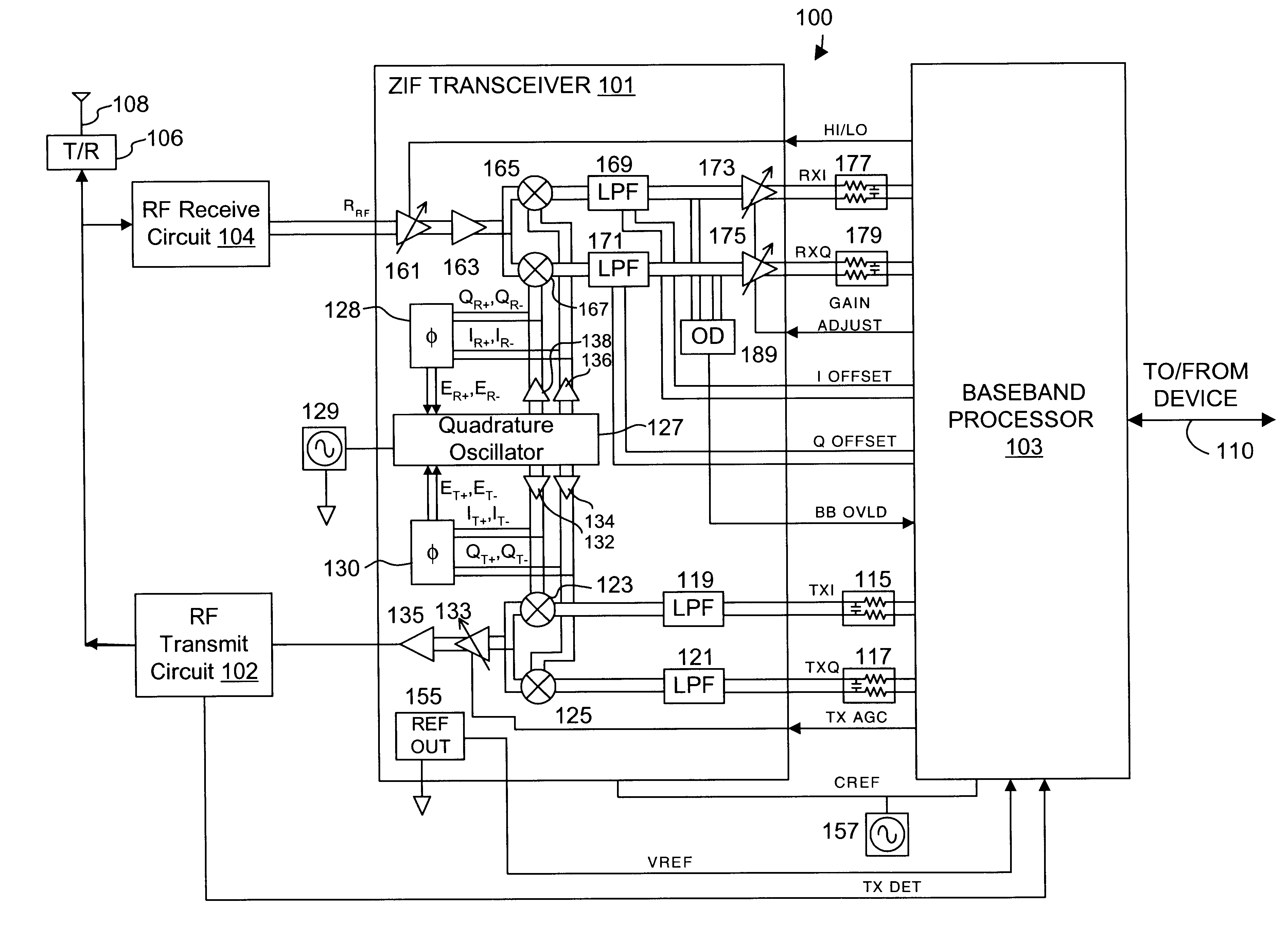
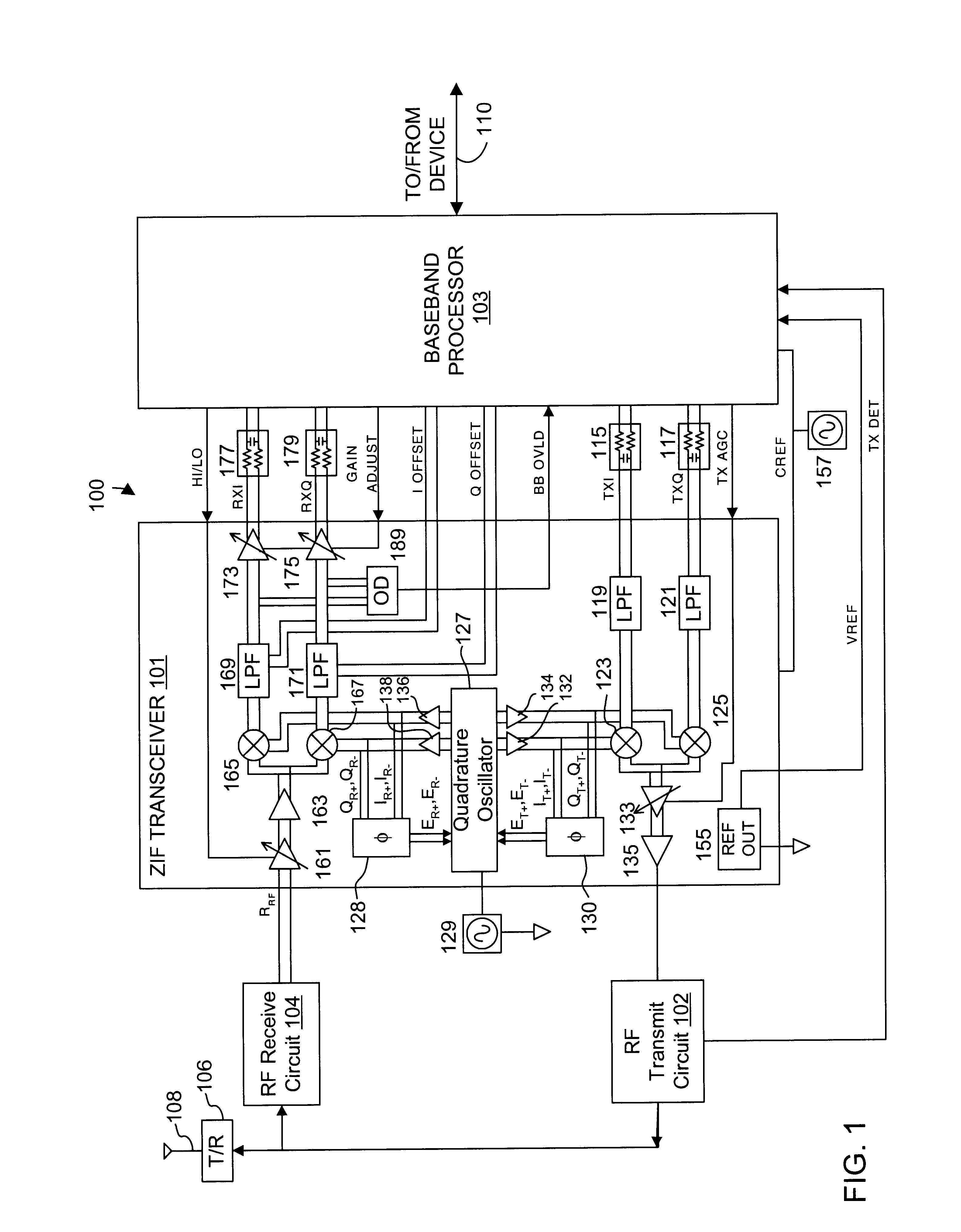
FIG. 1 is a simplified block diagram of an exemplary wireless transceiver 100 implemented according to an embodiment of the present invention. It is understood that the wireless transceiver 100 is applicable to WLAN configurations or any other type of radio or wireless communications for other types of applications. The wireless transceiver 100 is implemented as a zero intermediate frequency (ZIF) architecture including a ZIF transceiver 101, a baseband processor 103, a radio frequency (RF) transmit circuit 102, an RF receive circuit 104, a transmit / receive (T / R) switch 106, and an antenna 108. The ZIF architecture enables a simplified configuration by entirely eliminating intermediate frequency (IF) logic and associated circuitry. In this manner, only two primary modules, chips, or ICs (transceiver and processor) are utilized in the ZIF architecture to enable wireless communications. The ZIF transceiver 101 includes a quadrature oscillator 127 with phase error correction.

The wirele...


PUM


Abstract

An automatic gain control (AGC) amplifier including a high gain transimpedance amplifier, a resistive feedback network and multiple transconductance stages coupled in the feedback path of the AGC amplifier. The feedback network receives an input signal and is coupled to the output of the high gain amplifier and has multiple intermediate nodes. Each transconductance stage has an input coupled to an intermediate node of the feedback network and an output coupled to the input of the high gain amplifier. Each transconductance stage is independently controllable to position a virtual ground within the feedback network to control closed loop gain. Each transconductance stage may have a bias current input coupled to a bias current control circuit. The control circuit controls each bias current to vary the gain of the AGC amplifier. The bias currents may be linearly controlled employing a ramp function to achieve a linear in dB gain response.

Description

The present invention relates to gain control of amplifiers, and more particularly to a precision automatic gain control circuit.DESCRIPTION OF RELATED ARTAutomatic Gain Control (AGC) circuits are used in many communication and signal processing applications. For example, in the receiver of a wired or wireless communication link, the intended signal to be processed may be a short distance away and therefore relatively strong while another signal may be a long distance away and much weaker. The receiver must process both the strong signals and the weak signals which implies a variable gain function. High gain is used to detect and amplify weak signals and low gain and / or attenuation is used to process strong signals.The most simple gain stage that can implement an AGC function is the basic differential pair of transistors. An exemplary differential pair stage includes a pair of bipolar transistors Q1, Q2 having their emitters coupled together and to a bias current sink. A pair of loa...

Claims


Application Information

Patent Timeline
Patent Type & Authority Patents(United States)
IPC IPC(8): H03G7/00H03G7/06H03G3/30H03F3/45
CPCH03F3/45085H03G3/3052H03G7/06
Inventor PRENTICE, JOHN S.LANDY, PATRICK J.
Owner M RED INC
Why Eureka
Try Eureka