Multilayer feedthrough capacitor

a multi-layer, capacitor technology, applied in the direction of feed-through capacitors, fixed capacitor details, fixed capacitors, etc., can solve the problems of insufficient effect, inability to meet the higher frequency of recent years, and capacitors with large esls such as conventional multi-layer ceramic capacitors are increasingly becoming insufficient to handle the higher frequency

Inactive Publication Date: 2004-07-27
TDK CORPARATION
View PDF10 Cites 108 Cited by
  • Summary
  • Abstract
  • Description
  • Claims
  • Application Information

AI Technical Summary

Benefits of technology

According to the multilayer feedthrough capacitors according to the first and second aspects of the present invention, in addition to the intermediate internal conductors for grounding, there are first internal conductors and second internal conductors which signals etc. are input and output. Therefore, the capacitors of the present invention have array structures including two feedthrough capacitor elements. Therefore, it is possible to reduce both the noise of the common mode and the differential mode by just one multilayer feedthrough capacitor.
Further, in the first and second aspects of the present invention, currents flow in opposite directions in the first internal conductors and the second internal conductors. Therefore, due to the canceling action of the magnetic fields generated along with the flows of the high frequency currents in opposite directions in these internal conductors, inductance is suppressed, the ESL is further reduced, and the effect of elimination of noise in the high frequency band is improved.
In particular, in the second aspect of the present invention, an auxiliary second internal conductor is also arranged in the plane in which the first internal conductor is arranged and currents flow in opposite directions in these internal conductors. That is, currents flow in opposite directions in the two internal conductors arranged adjoining each other in the same plane. Therefore, the ESL is further reduced, and the effect of elimination of noise in the high frequency band is improved.
Further, in the aspect of the invention where one intermediate terminal electrode is arranged at each outside surface of the dielectric body, for a total of four, the terminal electrodes are arranged optimally at the outside surfaces of the capacitor body. Therefore, it becomes possible to effectively utilize the side surfaces of the capacitor body forming the multilayer feedthrough capacitor. Further, at least four intermediate terminal electrodes are connected to the interconnects of the external ground patterns. Along with this, the inductance at the branch parts of the intermediate internal conductors becomes smaller. As a result, the ESL is further reduced.

Problems solved by technology

Therefore, the noise produced from these devices also tends to increase more in the high frequency band.
In multilayer ceramic capacitors, however, the parasitic component, that is, the ESL, obstructs the noise eliminating effect in the high frequency band, so the effect has become insufficient along with the increasingly higher frequencies of the operating frequencies of electronic equipment.
That is, capacitors having large ESLs such as the conventional multilayer ceramic capacitors are increasingly becoming unable to sufficiently handle the higher frequencies of recent years.
Therefore, such conventional multilayer feedthrough capacitors 110 are increasingly becoming unable to handle the higher frequencies of recent years and capacitors able to reduce the ESL further are becoming required.
These publications, however, do not disclose the idea of passing currents in opposite directions in internal conductors adjacent in the stacking direction so as to reduce the ESL.
However, these publications do not disclose that it is possible to reduce the noise of both the common mode and the differential mode in a multilayer feedthrough capacitor and to further reduce the ESL so as to improve the effect of elimination of high frequency noise.

Method used


Image

  • Multilayer feedthrough capacitor
  • Multilayer feedthrough capacitor
  • Multilayer feedthrough capacitor

Examples


Embodiment Construction

Next, the results of measurement of the attenuation characteristics and ESL of the following samples by a network analyzer will be shown.

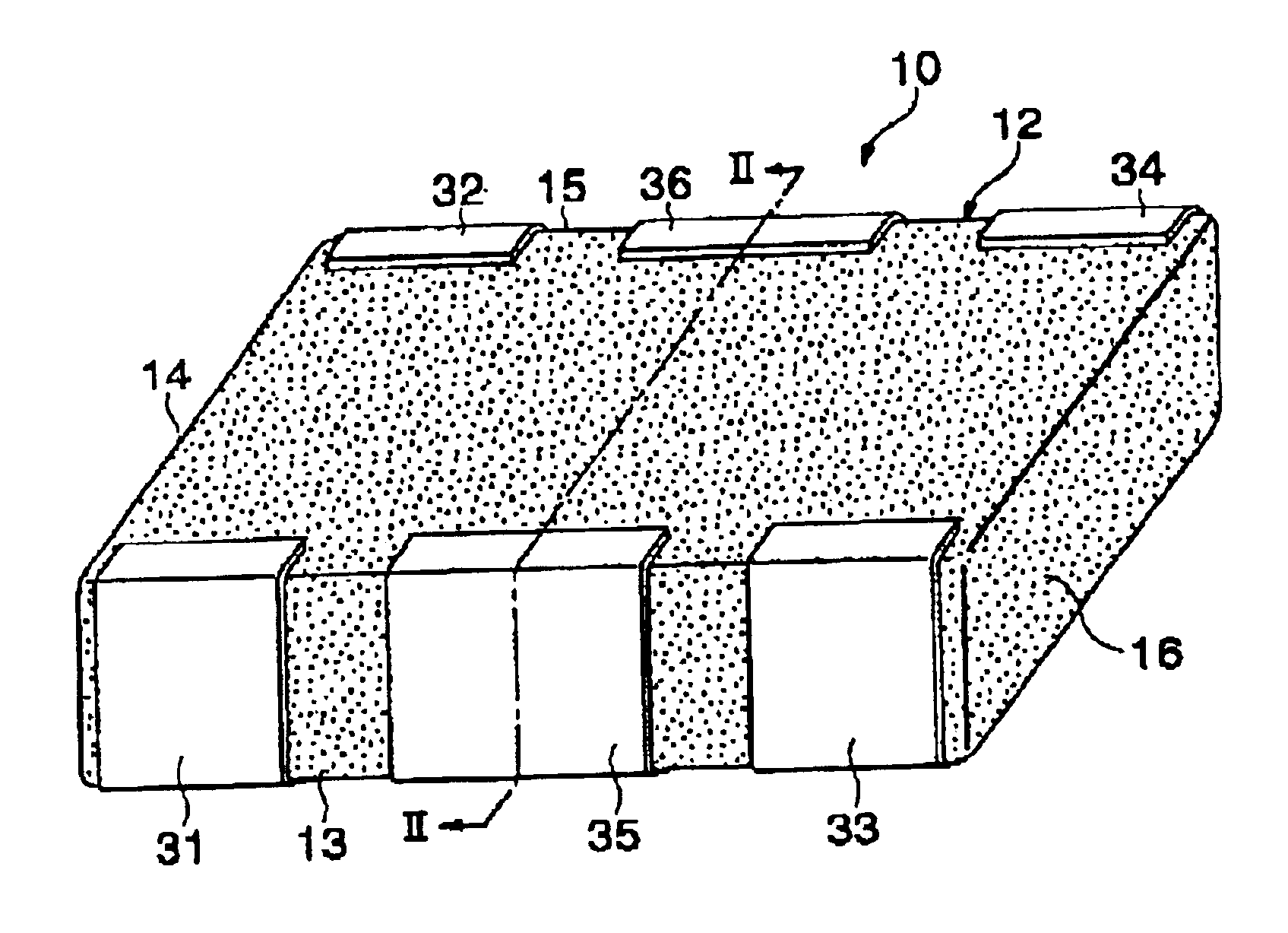
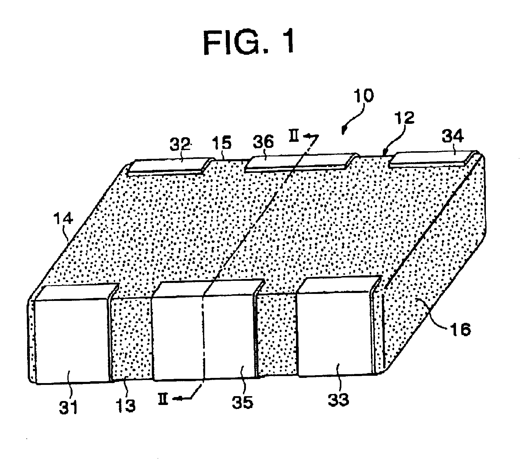
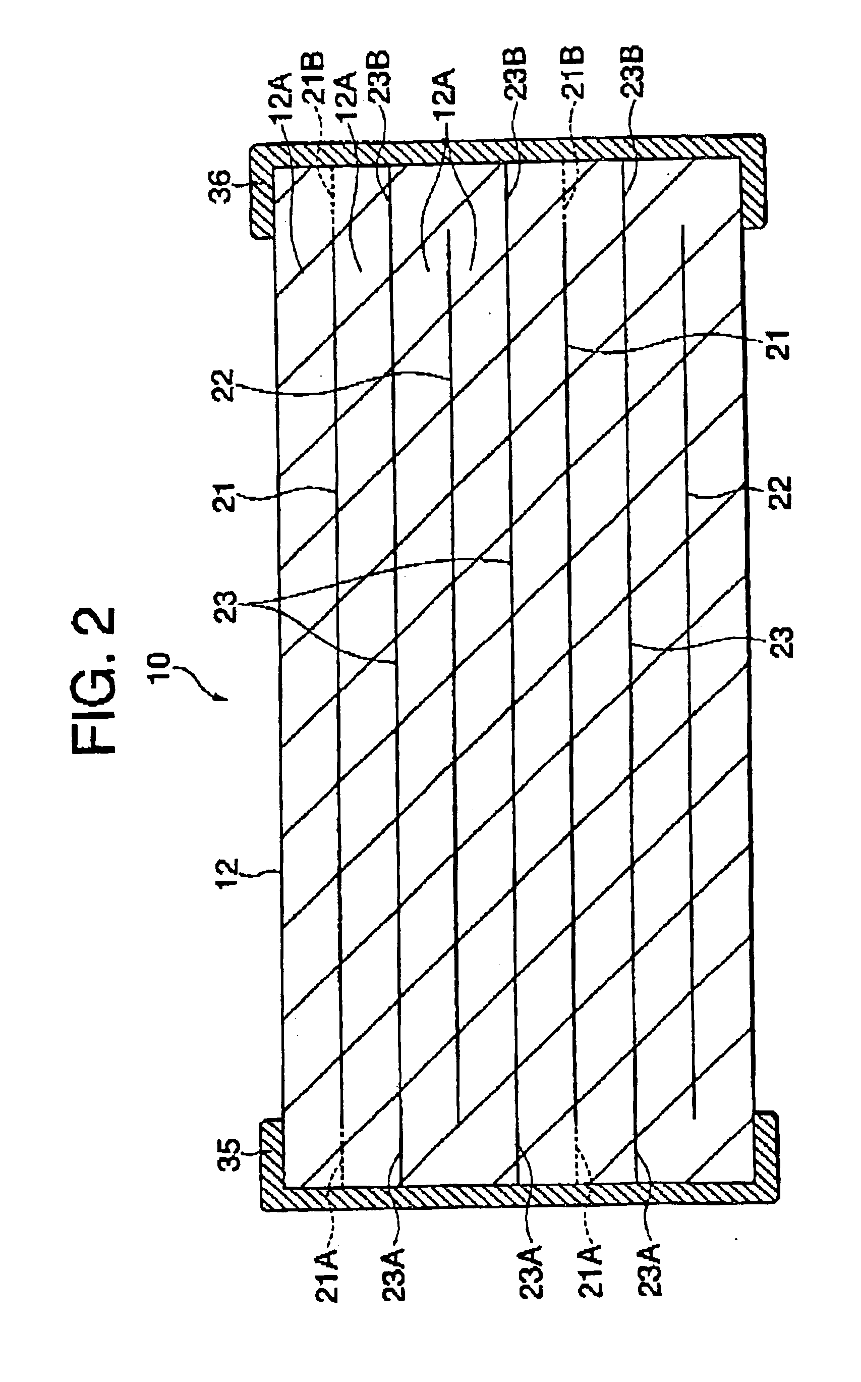
The multilayer feedthrough capacitor 10 of the first embodiment shown in FIG. 1 to FIG. 3 and multilayer feedthrough capacitors 110 of the prior art shown in FIG. 12 to FIG. 13 were prepared as experimental samples. These samples were measured for attenuation characteristics and ESL etc.

At the time of the experiment, as shown by the circuit diagram of FIG. 9A, the multilayer feedthrough capacitor 10 of the first embodiment was connected to the input / output ends of the not shown network analyzer, that is, Port 1 and Port 2, for measurement. Further, as shown in the circuit diagram of FIG. 9B, two multilayer feedthrough capacitors 110 of the prior art were connected in the same way to the Port 1 and Port 2 of the network analyzer for measurement.

As a result of the measurement, as shown by the graph of the attenuation characteristics shown in FIG. 8, ...


PUM

PropertyMeasurementUnit
currentsaaaaaaaaaa
currentsaaaaaaaaaa
frequencyaaaaaaaaaa

Abstract

A multilayer feedthrough capacitor having a first internal conductor arranged in a dielectric body, an intermediate internal conductor arranged in the dielectric body and stacked with the first internal conductor via a ceramic layer, a second internal conductor arranged in the dielectric body and stacked with the intermediate internal conductor via a ceramic layer, a first terminal electrode formed at an outside surface of the dielectric body and connected to the first internal conductor, a second terminal electrode formed at the outside surface of the dielectric body and connected to the second internal conductor, and an intermediate terminal electrode formed at the outside surface of the dielectric body and connected to the intermediate internal conductor. The intermediate terminal electrode is connected to the ground, while the first terminal electrode and the second terminal electrode are connected to paths for transmitting signals. The first internal conductor and the second internal conductor have currents flowing through them in opposite directions.

Description

1. Field of the InventionThe present invention relates to a multilayer feedthrough capacitor used in a noise filter etc. designed not only to deal with noise of the common mode and noise of the differential mode, but also to reduce the equivalent serial inductance (ESL) more and thereby effectively eliminate noise in the high frequency band, more particularly one suitable for an information processing device or communications device.2. Description of the Related ArtIn recent years, the majority of information processing devices and communications devices have become digitalized. Further, along with the higher speeds of processing accompanying the improvements in information processing capabilities, there has been remarkable progress in raising the frequencies of the digital signals handled by these devices. Therefore, the noise produced from these devices also tends to increase more in the high frequency band. On the other hand, efforts are being made to make these devices more port...

Claims


Application Information

Patent Timeline
Patent Type & Authority Patents(United States)
IPC IPC(8): H01G4/35H01G4/12H01G4/228H01G4/232H01G4/30
CPCH01G4/232H01G4/30H01G4/35
Inventor TOGASHI, MASAAKI
Owner TDK CORPARATION
Why Eureka
Try Eureka