
High speed access bus interface and protocol

a high-speed access and bus technology, applied in bus networks, digital transmission, data switching networks, etc., can solve the problems of increasing the amount of work per packet, occupying processing resources, and physical size reductions that cannot continue indefinitely, and limit the ability to continuously increase the processor clock speed

Inactive Publication Date: 2004-08-17
AVAYA MANAGEMENT LP
View PDF13 Cites 24 Cited by
  • Summary
  • Abstract
  • Description
  • Claims
  • Application Information

AI Technical Summary

Benefits of technology

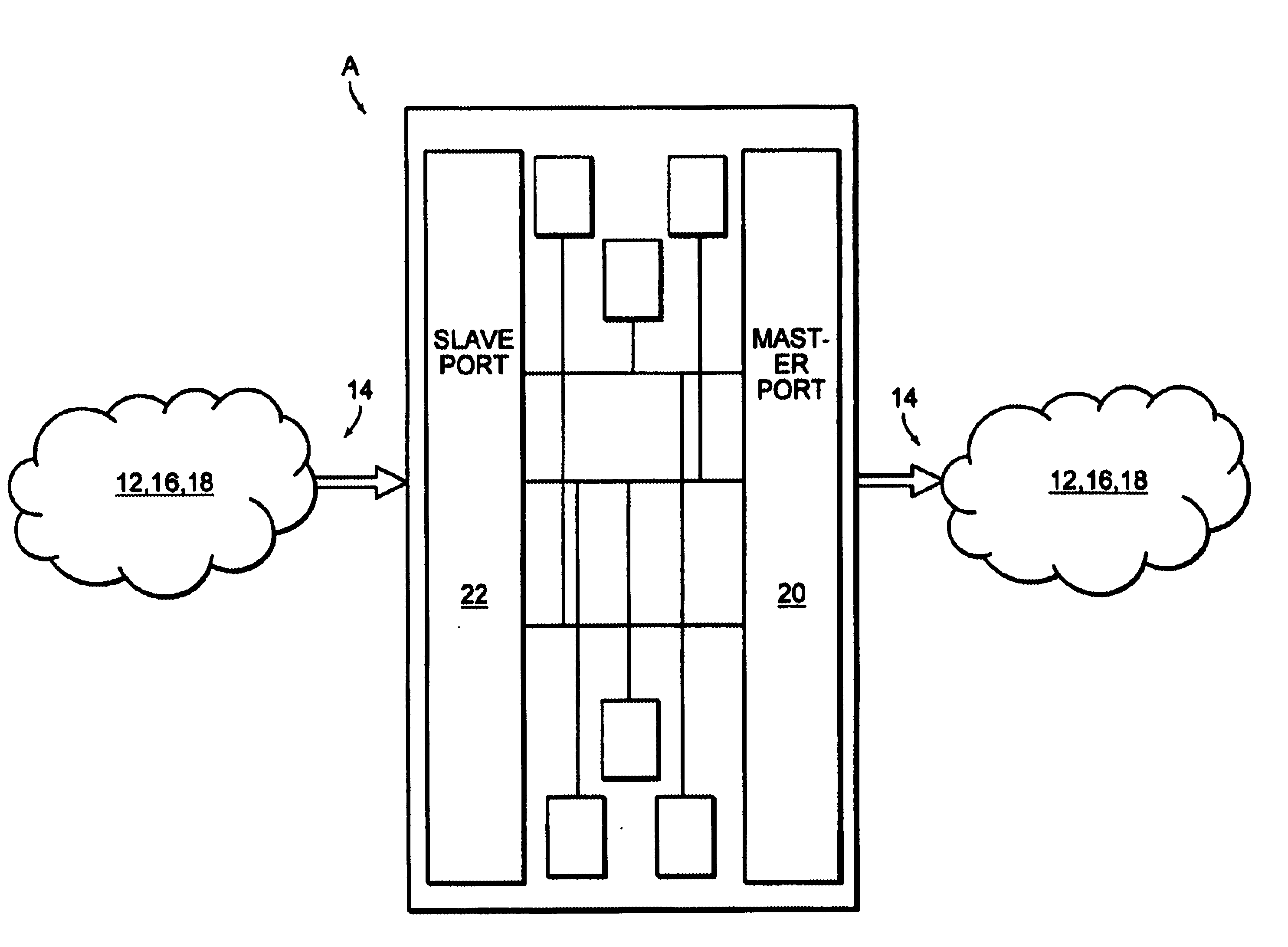
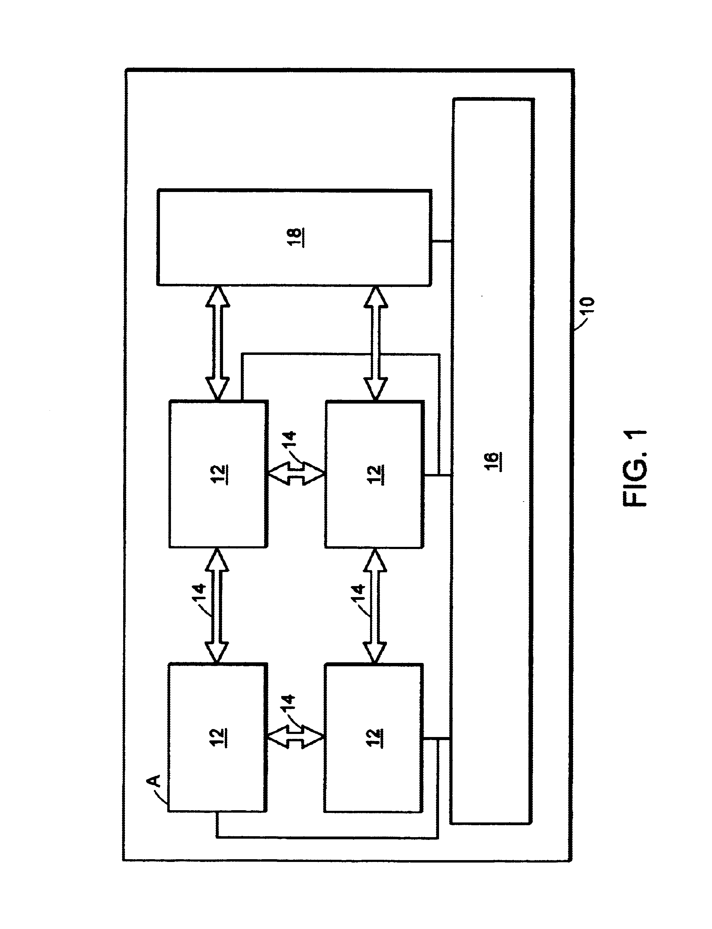
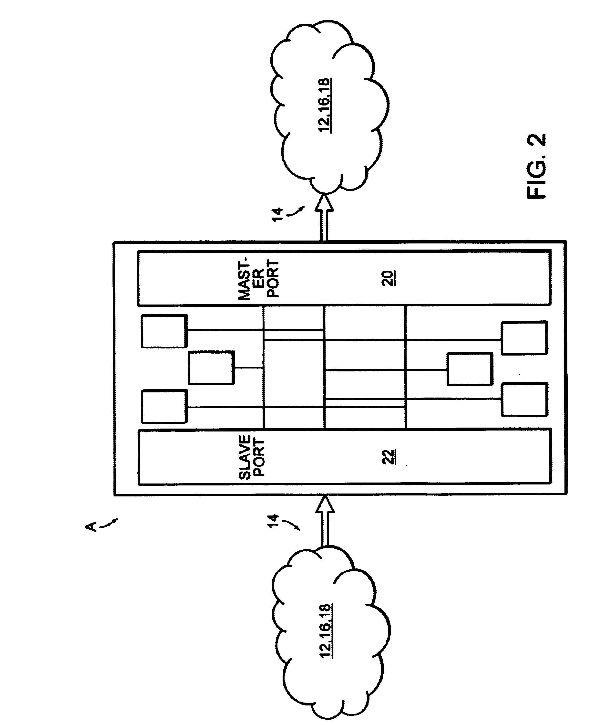
The present invention is configured to provide a fast path data packet transfer across a bus infrastructure in a switching mechanism. As such, the present invention includes a first port and a second port on each processor for establishing a uni-directional data flow path. The present invention further includes a synchronous clocking pulse generator for synchronizing the transfer of the data packets from the first port of a first processor to the second port of a second processor. This allows for fast chip to chip source synchronization, where each chip has a sourcing clock generator.

Problems solved by technology

Moreover, such demands are exacerbated by the advent of policy-based networking, which requires more data packet processing, thereby increasing the amount of work per packet and occupying processing resources.
It is commonly understood, however, that physical size reductions cannot continue indefinitely and there are limits to continually increasing processor clock speeds.
The IP fast forwarding problem is becoming harder as the amount of time allotted for processing on a per packet basis steadily decreases in response to increasing media transmission speeds.

Method used


Image

  • High speed access bus interface and protocol
  • High speed access bus interface and protocol
  • High speed access bus interface and protocol

Examples


Embodiment Construction

The innovative teachings of the present application will be described with particular references to the present embodiments. However, it should be understood that this class of embodiments provides only a few examples of the many advantageous uses of the innovative teachings described herein. In general, statements made in the specification of the present application do not necessarily delimit any of the various claimed inventions. Moreover, some statements may apply to some inventive features but not to others.

The present invention generally relates to communication system architecture and, more particularly, to packet processing architecture employed within a communication network that provides fast path processing and enhanced flexibility / adaptability of packet processors. The inventive packet processing architecture will hereinafter be referred to as packet router mechanism.

Referring now to the drawings in greater detail, FIG. 1 shows a block diagram of a packet router host mech...


PUM


Abstract

A high speed access bus interface for a communications network. The interface allows uni-directional transfer of data packets at a fast path processing rate of about 10 gigabits per second. The interface uses a master port and a slave port in a chip to chip data transfer scheme. The master and slave ports may have one or more than one data channel for transferring data packets. The master port includes a clock signal for synchronizing the transfer from the master port to the slave port. The slave may send an asynchronous signal to the master port in order to initiate the master port to stop or stall the pipeline transfer of data packets until space is made available in the slave port buffer. In addition to the clock synchronization, the interface utilizes an enable signal, a start of packet signal, an end of packet signal, an error signal (if necessary), a last valid byte signal, and a parity bit signal to identify, address, each data packet in the data stream. If a processing error occurs, the master port error signal to the slave port also initiates the slave port to disregard the previous data packet. The operating frequency of 50 MHz allows the data packet transfer to exceed 10 gigabits per second.

Description

1. Field of the InventionThis invention generally relates to the field of data communications and data processing architectures. More particularly, the present invention relates to a high speed chip to chip interface and protocol for fast path processing of data packets in a route switch mechanism.2. Description of Related Art and General BackgroundThe unprecedented growth of data networks (e.g., corporate-wide Intranets, the Internet, etc.) as well as the development of network applications (e.g., multimedia, interactive applications, proprietary corporate applications, etc.) have resulted in creating a demand for higher network bandwidth capabilities and better network performance. Moreover, such demands are exacerbated by the advent of policy-based networking, which requires more data packet processing, thereby increasing the amount of work per packet and occupying processing resources. One approach to increase network bandwidth and improving network performance is to provide for...

Claims


Application Information

Patent Timeline
Patent Type & Authority Patents(United States)
IPC IPC(8): H04L12/46
CPCH04L12/4641
Inventor BROWN, BENJAMIN J.MODELSKI, RICHARD P.ROY, JOHN P.
Owner AVAYA MANAGEMENT LP
Learn More