
Method of treating arsenic-contaminated waters

a technology of arsenic and water, applied in the direction of silicon compounds, other chemical processes, separation processes, etc., can solve the problems of significant contamination, high concentration of arsenic in drinking water, and similar problems

Inactive Publication Date: 2004-09-14
CHK GROUP
View PDF20 Cites 27 Cited by
  • Summary
  • Abstract
  • Description
  • Claims
  • Application Information

AI Technical Summary

Benefits of technology

NZNPF effectively reduces arsenic levels from contaminated waters to below detection limits within 30 minutes, maintaining water quality and aesthetics, with reduced operational costs and infrastructure needs, and allows for easy disposal of arsenic-containing sludge.

Problems solved by technology

High concentrations of arsenic in drinking water result from either anthropogenic contamination or weathering of naturally occurring subsurface materials.
Furthermore, use of arsenic species in manufacturing of sulfuric acid and leather tanning have resulted in significant contamination.
A similar problem was encountered in towns of Buxton and Hollis, Me.
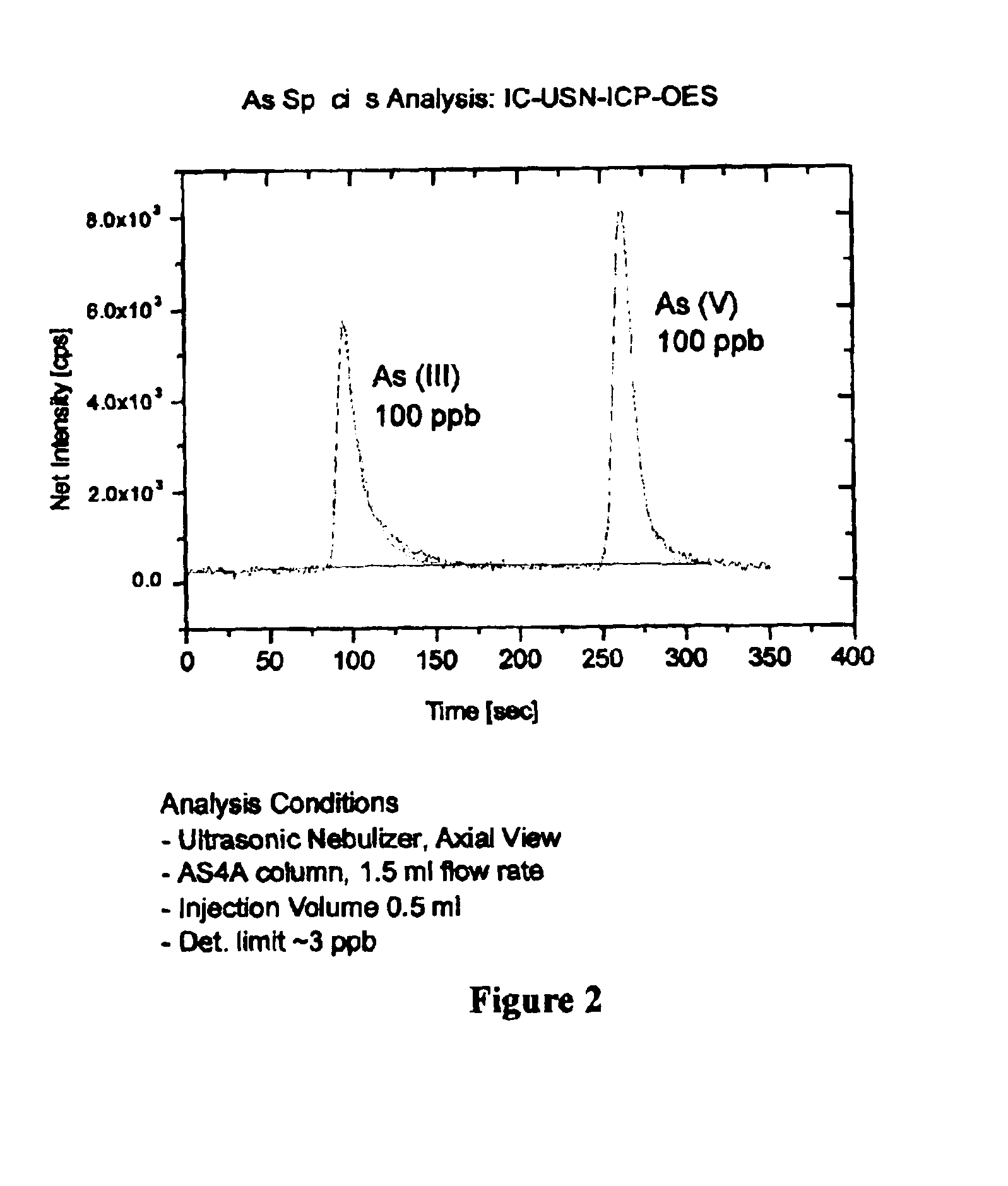
As(III) in the concentration of 100 ppb is extremely toxic and may cause skin cancer and neurological damage.
All these technologies are good only for As(V) and very little data is available for As(III).

Method used


Image

  • Method of treating arsenic-contaminated waters
  • Method of treating arsenic-contaminated waters
  • Method of treating arsenic-contaminated waters

Examples


example 2

Si-Ferrihydrite with Si / Fe Molar Ratio of 0.04

To a 1000 mL beaker containing 100 mL of 1 M FeCl.sub.3, 100 mL of 0.04 M Na.sub.2 SiO.sub.3 was added and solutions mixed using a magnetic stirrer. The pH of the solution was raised to 8.2, which resulted in formation of precipitate. The precipitate was incubated for a day; subsequently, the sample was centrifuged and dialyzed to remove excess of salts. The freeze-dried sample was used for characterization.

example 3

Si-Free Birnessite

To a 1000-mL beaker containing 200 mL of 0.5 M MnSO.sub.4, 250 mL of 5.2 M NaOH was added rapidly and the resulting black precipitate was agitated using a magnetic stirrer. Oxygen was immediately passed through the precipitate at a rate of 2 L min.sup.-1 using a fritted glass tube to produce a stream of small bubbles. After 5 h, the black suspension was centrifuged at 10,000 rpm for 30 min. The first supernatant was saved to determine the NaOH concentration and / or its consumption. The sample was further washed with deionized water five times and dialyzed. The freeze-dried sample was used for characterization.

example 4

Si-Birnessite with Si / Mn Molar Ratio Ranging from 0.32 to 0.68

Silica was added to the birnessite synthesis, to make it poorly crystalline so that high surface area would provide more interaction of Mn(II) with As(III) resulting in higher oxidation of the latter ions. To a 1000-mL beaker containing 200 mL of 0.5 M MnSO.sub.4, 250 mL of 5.2 M NaOH containing appropriate amount of dissolved Na.sub.2 SO.sub.3.5H.sub.2 O was added rapidly to achieve the desired Si / Mn molar ratio and the resulting black precipitate was agitated using a magnetic stirrer. Oxygen was immediately passed through the precipitate at a rate of 2 L min.sup.-1 using a fritted glass tube to produce a stream of small bubbles. After 5 h, the black suspension was centrifuged at 10,000 rpm for 30 min. The first supernatant was saved to determine the NaOH concentration and / or its consumption. The sample was further washed with deionized water five times and dialyzed. The freeze-dried sample was used for characterization....


PUM

PropertyMeasurementUnit
concentrationaaaaaaaaaa
particle sizeaaaaaaaaaa
unit cell dimensionsaaaaaaaaaa

Abstract

The present invention is directed to an adsorbent for removing arsenic species from ground water and / or surface water systems. Such adsorbent removes both As(III) and As(V), thereby providing potable water. Also provided is a method and / or device (e.g., filter) for removing arsenic species from contaminated waters utilizing such adsorbent.

Description

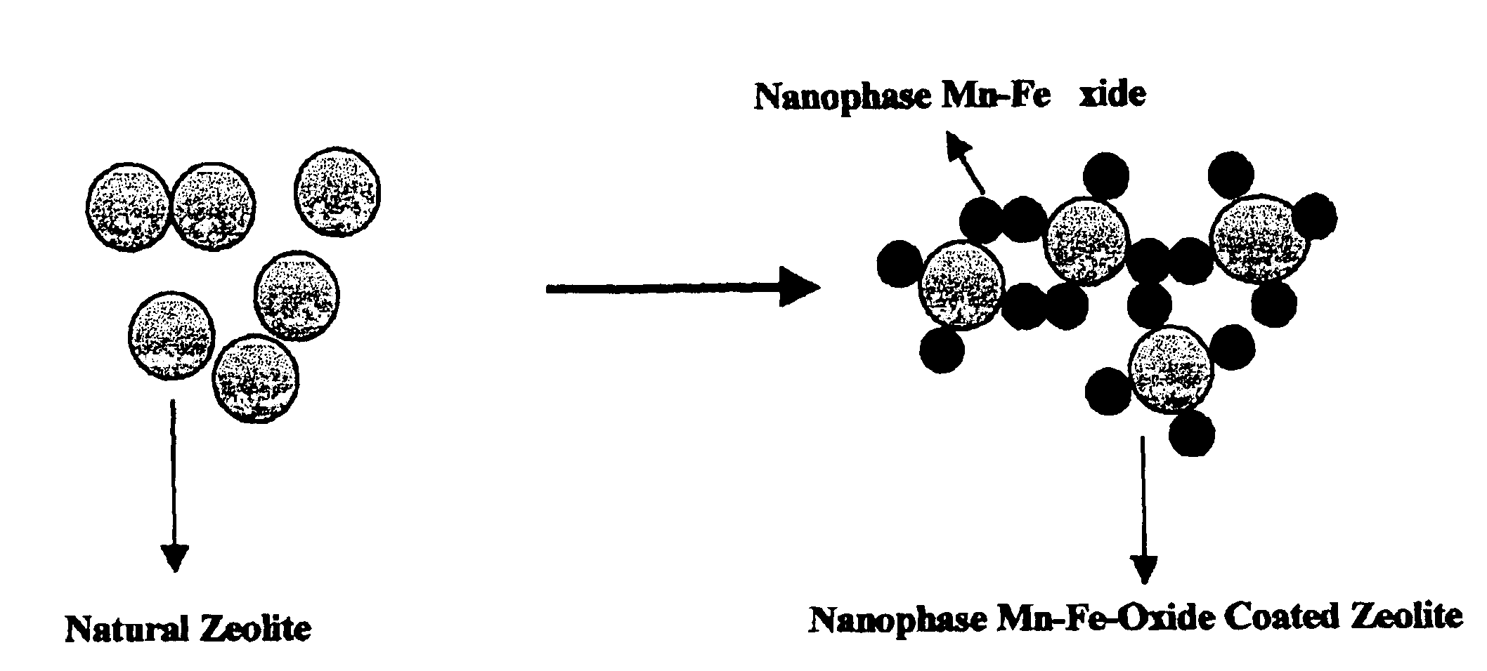
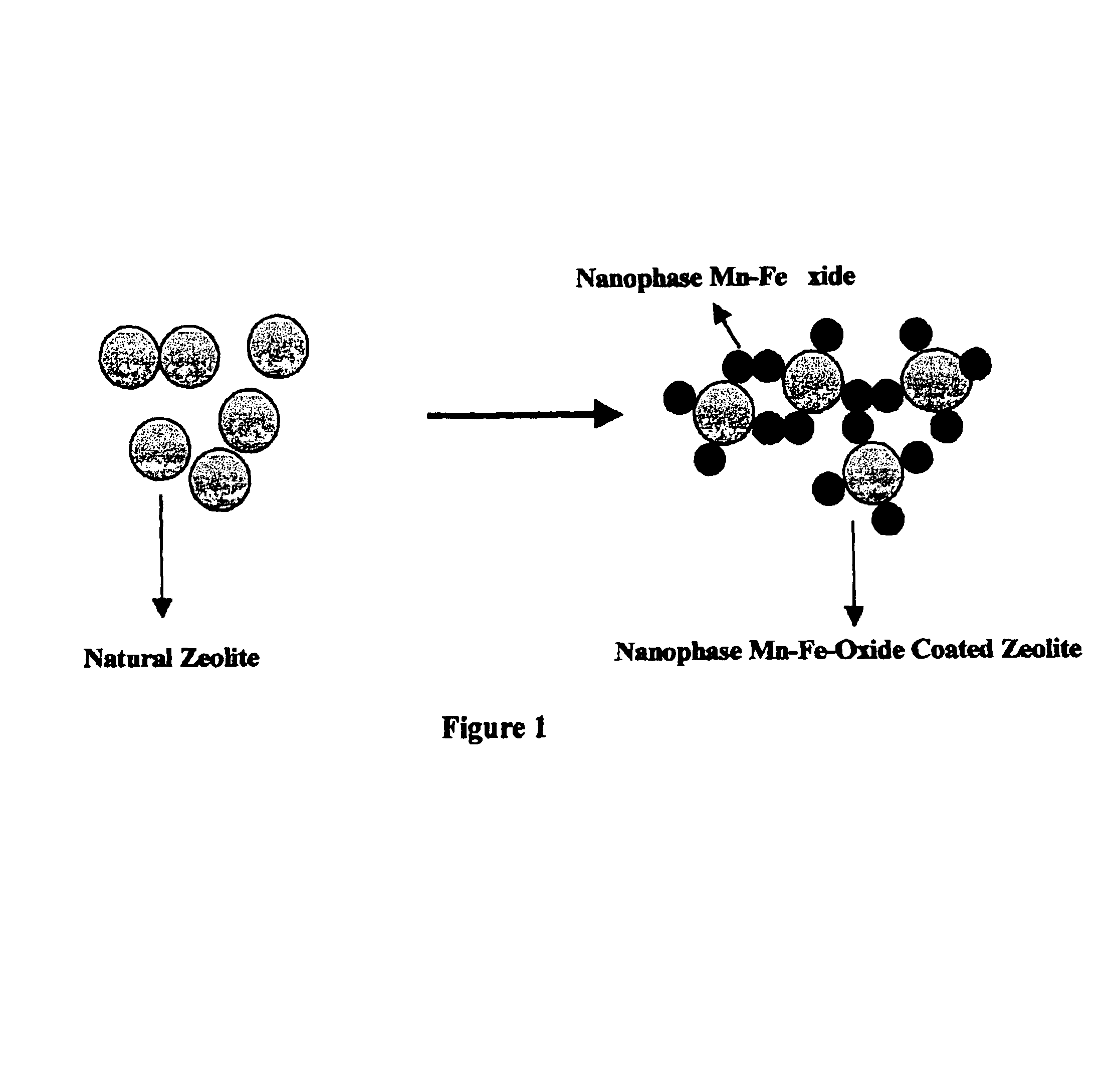
The present invention relates to an adsorbent for arsenic species and a method and / or device for removing arsenite (As(III)) and arsenate (As(V)) from ground water and surface water systems. Particularly, the present invention relates to natural zeolite coated with nanophase Mn--Fe oxides (NZNPF), and a method and / or device for removing As(III) and As(V) from arsenic-contaminated waters using NZNPF.DESCRIPTION OF THE PRIOR ARTHigh concentrations of arsenic in drinking water result from either anthropogenic contamination or weathering of naturally occurring subsurface materials. The two most important anthropogenic sources of arsenic are agricultural chemicals and wood preservatives. Furthermore, use of arsenic species in manufacturing of sulfuric acid and leather tanning have resulted in significant contamination. In the geological occurrence, arsenic is found at high levels in primary sulfide minerals, such as arsenopyrite (FeAsS), pyrite (FeS.sub.2), pyrrhotite (Fe.sub.1-x S), orp...

Claims


Application Information

Patent Timeline
Patent Type & Authority Patents(United States)
IPC IPC(8): B01J20/06B01J20/18B01J20/32B01J20/10B01J20/30C02F1/28C02F1/72C02F1/66
CPCB01J20/0222B01J20/0229B01J20/06B01J20/165B01J20/183B01J20/3234B01J20/3236B01J20/3295C02F1/281C02F1/288B01J2220/42C02F1/66C02F1/72C02F2101/103C02F2103/06Y10S210/911
Inventor VEMPATI, RAJAN K.
Owner CHK GROUP
Learn More