Thin film magnetic head and magnetic storage apparatus

magnetic storage technology, applied in the field of thin film magnetic heads and magnetic storage apparatuses, can solve the problem of not having a thin film magnetic head capable of generating a strong magnetic field sufficient for writing to high-coercivity media

Inactive Publication Date: 2004-09-21
HITACHI GLOBAL STORAGE TECH JAPAN LTD
View PDF2 Cites 6 Cited by
  • Summary
  • Abstract
  • Description
  • Claims
  • Application Information

AI Technical Summary

Benefits of technology

Therefore, in the present invention, Bs of the first magnetic layer is set higher than Bs of the second magnetic layer. By such composition, the gap part of the head is prevented from being saturated before the upper magnetic pole, thereby various problems in conventional magnetic recording heads (serious decrease in the magnetic field gradient, rapid deterioration of characteristics at high frequencies, etc.) can be resolved.
By the employment of a CoNiFe layer or a CoFe layer also for the second magnetic layer, the second magnetic layer is allowed to have excellent crystallinity and thereby the control of the orientation can be made easier. When different types of metals are stacked up, the so-called cell reaction tends to occur and there is a possibility of corrosion of the second magnetic layer containing CoNiFe, however, such corrosion is avoided if the first magnetic layer also contains CoNiFe as in the present invention.
By the thin film magnetic head which is composed as above, the writing to a recording medium of a coercivity of 4000 Oe or more is made possible.

Problems solved by technology

However, such a technique for the formation of a stable and thick magnetic core has not been established yet at present, and thus there has been realized no thin film magnetic head that is capable of generating a strong magnetic field sufficient for the writing to the high-coercivity medium.

Method used


Image

  • Thin film magnetic head and magnetic storage apparatus
  • Thin film magnetic head and magnetic storage apparatus
  • Thin film magnetic head and magnetic storage apparatus

Examples


Embodiment Construction

Referring now to the drawings, description will be given in detail of embodiments in accordance with the present invention.

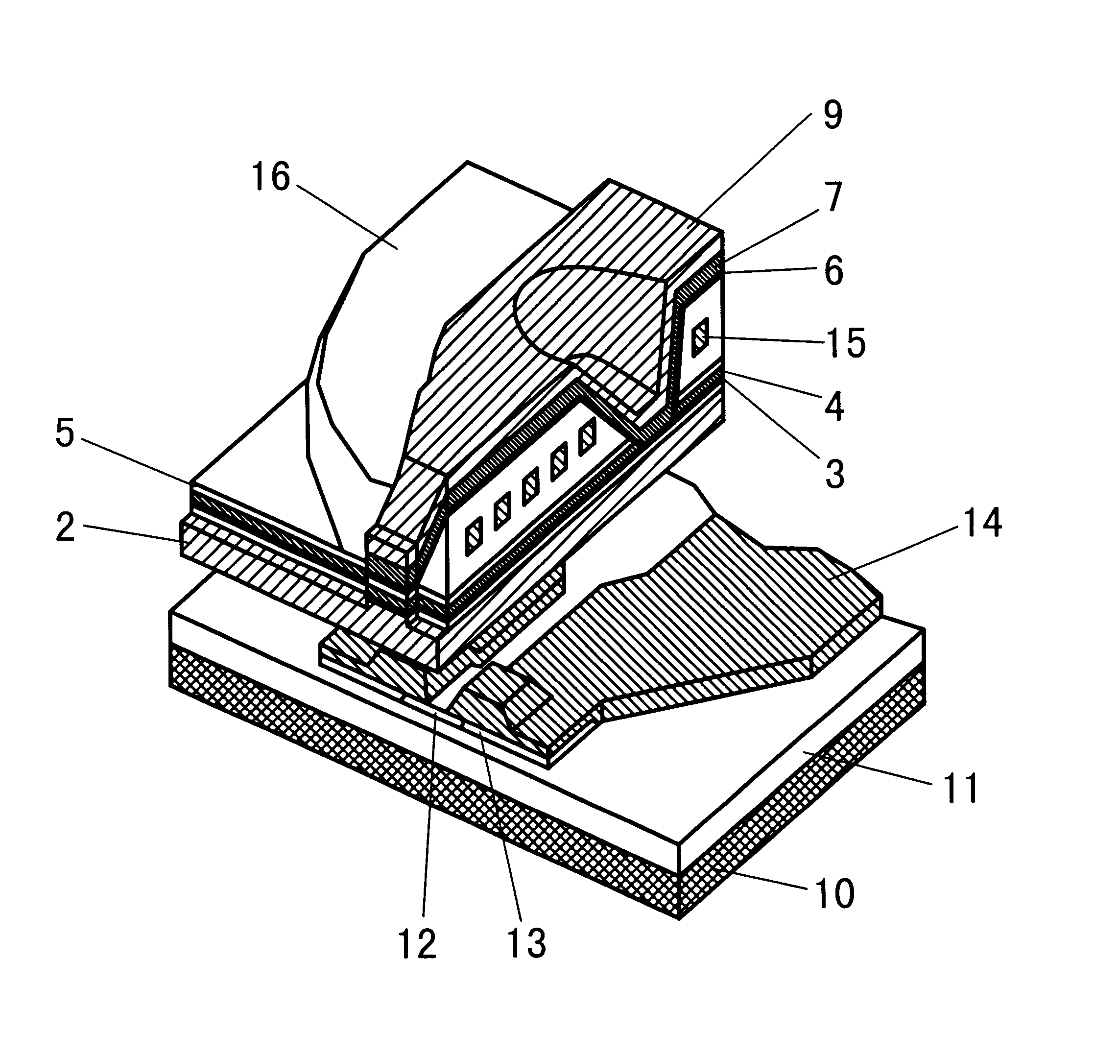
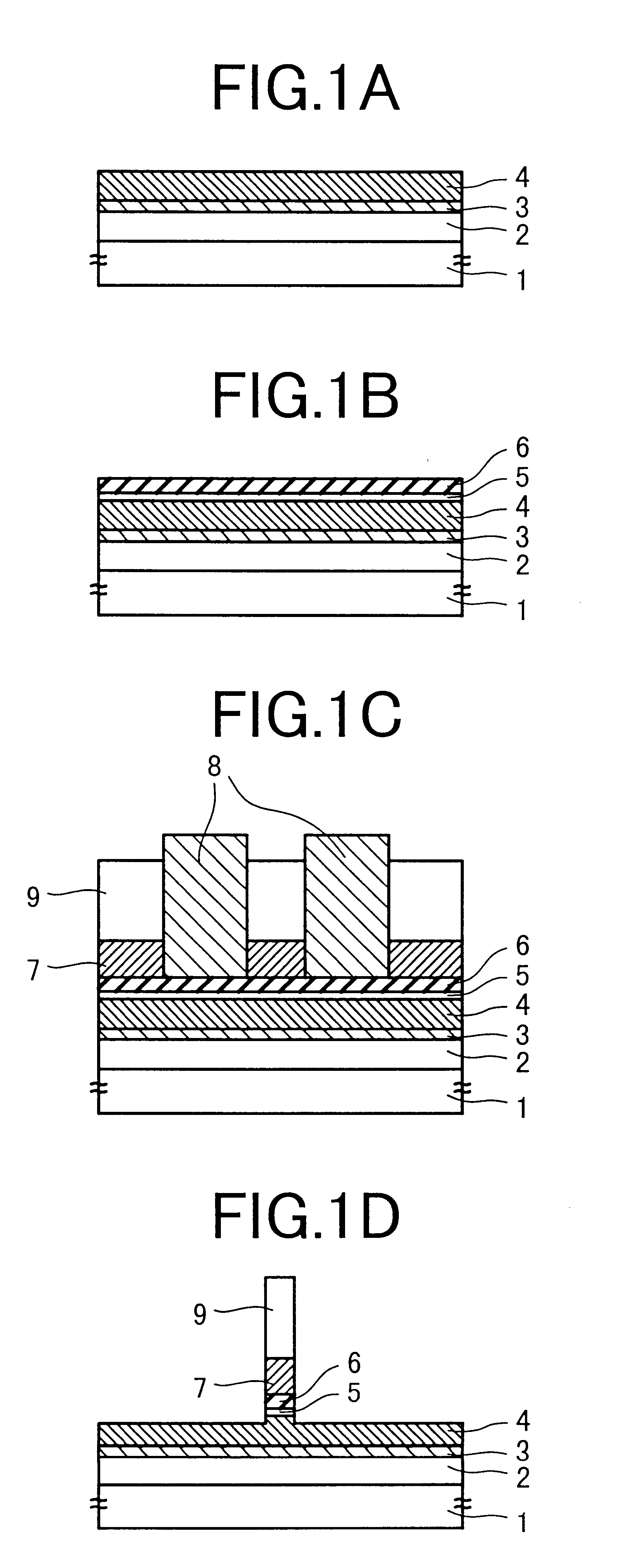
The thin film magnetic head in accordance with the present invention constitutes a lower magnetic pole, an upper magnetic pole which is provided so as to face the lower magnetic pole, and a magnetic gap layer which is provided between the lower magnetic pole and the upper magnetic pole. The upper magnetic pole constitutes a first magnetic layer which is formed on a side facing the magnetic gap layer by means of sputtering and a second magnetic layer which is formed on the first magnetic layer by means of plating, in which the saturation magnetic flux density of the first magnetic layer is set higher than that of the second magnetic layer.

In the present situation in magnetic recording heads with the recording head track width of 1 .mu.m or less and the gap layer thickness of 0.2 .mu.m due to the increasing recording density, sufficient recording magnetic field mi...


PUM

PropertyMeasurementUnit
saturation magnetic flux densityaaaaaaaaaa
thicknessaaaaaaaaaa

Abstract

A thin film magnetic head includes a lower magnetic pole, an upper magnetic pole provided so as to face the lower magnetic pole, and a magnetic gap layer provided between the lower magnetic pole and the upper magnetic pole. The upper magnetic pole constitutes a first magnetic layer formed on a side facing the magnetic gap layer by means of sputtering and a second magnetic layer formed on the first magnetic layer by means of plating, in which the saturation magnetic flux density of the first magnetic layer is set higher than that of the second magnetic layer. The thin film magnetic head composed as above is capable of generating a stronger magnetic field owing to its stably-formed magnetic core, thereby recording on a high-coercivity medium and high-density recording are made possible.

Description

1. Field of the InventionThe present invention relates to a thin film magnetic head which is used for the recording / reproducing on a magnetic recording medium, a method for manufacturing the thin film magnetic head, and a magnetic storage apparatus including the thin film magnetic head.2. Description of the Related ArtWith the increase of the recording density of magnetic storage apparatuses, coercivity required of recording media is also advancing higher and higher, and as magnetic core material for recording heads, materials having high saturation magnetic flux density (Bs), that is, materials capable of outputting a strong magnetic field sufficient for the writing to the high-coercivity medium, are being required. Such materials having high saturation magnetic flux density (Bs) include CoNiFe (Bs: 1.7 T) whose Bs is higher than that of Ni.sub.45 Fe.sub.55 (Bs: 1.6 T) which is being generally used as magnetic core material, as described in JP-A-6-89422, JP-A-8-241503, JP-A-6-34620...

Claims


Application Information

Patent Timeline
Patent Type & Authority Patents(United States)
IPC IPC(8): G11B5/31
CPCG11B5/3109G11B5/313G11B5/3163Y10T29/49032G11B5/3146
Inventor KUDO, KAZUEOKADA, YASUYUKIFUYAMA, MORIAKIMARUYAMA, YOHJIOIKAWA, GEN
Owner HITACHI GLOBAL STORAGE TECH JAPAN LTD
Why Eureka
Try Eureka