
Reduced capacitance AC/DC/AC power converter

a power converter and capacitance reduction technology, applied in the direction of ac-ac conversion, power conversion systems, electrical apparatus, etc., can solve the problems of capacitor explosion, serious damage to other components of the power converter, and large capacitance electrolytic capacitors which must withstand a high level of dc voltag

Inactive Publication Date: 2004-10-12
WICON
View PDF13 Cites 94 Cited by
  • Summary
  • Abstract
  • Description
  • Claims
  • Application Information

AI Technical Summary

Benefits of technology

It is the objective of the present invention to construct AC / DC / AC power converter systems without using any electrolytic capacitor, such that the converter is more compact, durable and reliable. These converter systems only require a small capacitance easily obtainable with other types of capacitors such as film or ceramic type. The system further includes means to disconnect both input and output to the DC bus capacitor. A controller capable of fast monitoring the DC bus voltage is also part of the system. The controller is also able of quickly disconnecting the capacitor out of either input or output energy path to prevent the capacitor from being charged to over-voltage. The controller further possesses capability of re-connecting the disrupted energy path once the DC bus capacitor voltage returns to normal.

Problems solved by technology

There are drawbacks of conventional power converter using electrolytic capacitors:
A large capacitance electrolytic capacitor which must withstand a high level of DC voltage has a relatively limited operating lifetime.
Breakdown of such an electrolytic capacitor can cause serious damage to other components of the power converter, since leakage of corrosive electrolyte may occur, or the capacitor may even explode.
These additional components increase not only cost but also board space to mount them.
The smoothing electrolytic capacitors occupy a relatively large amount of space within the power converter, thereby reducing the freedom available for mechanical design of the converter, and causing the overall size of the power converter to be large.
If we assume that the energy storage component (in this case battery or fuel cell in stead of electrolytic capacitors) is taken away from the circuit, there is little energy storage capability left by the film capacitor on the DC link.
In this case the DC link is easily over charged, resulting in DC link over-voltage.
This over voltage may damage the converter components such as the switching transistors.
Thus their solution is not readily applicable to a conventional AC power converter with a diode front end rectifier.
Additionally this technique limits the output voltage transfer ratio to 0.866 which is not tolerable to most of the AC power converter products.
Complexity and part counts are increased and hence also the cost.
Cost again is an issue for those applications that do not require regenerative feature.
Besides the system suffers poor efficiency, additional diode and resistor also offset the cost saving from the reduction of electrolytic capacitance.
Such arrangement is not able to deliver storage energy from the electrolytic capacitors during ride-through.
The resultant power converter is costly, less efficient as well as bulky.
Both configurations results in either regulated or slow moving DC bus voltage.
DC bus voltage feedback quality by conventional controller deteriorates significantly during fast bus voltage transient.
Now it becomes apparent that none of above solutions is suitable or adequate to make a reduced capacitance DC / AC inverter capable of working with a non-regenerative diode rectifier.

Method used


Image

  • Reduced capacitance AC/DC/AC power converter
  • Reduced capacitance AC/DC/AC power converter
  • Reduced capacitance AC/DC/AC power converter

Examples


Embodiment Construction

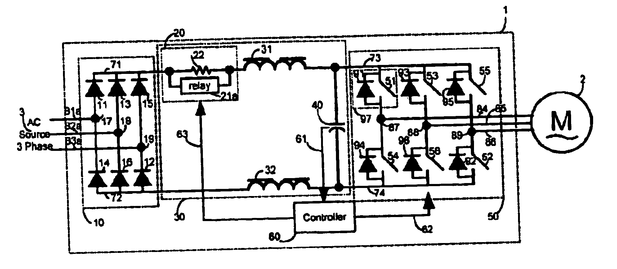
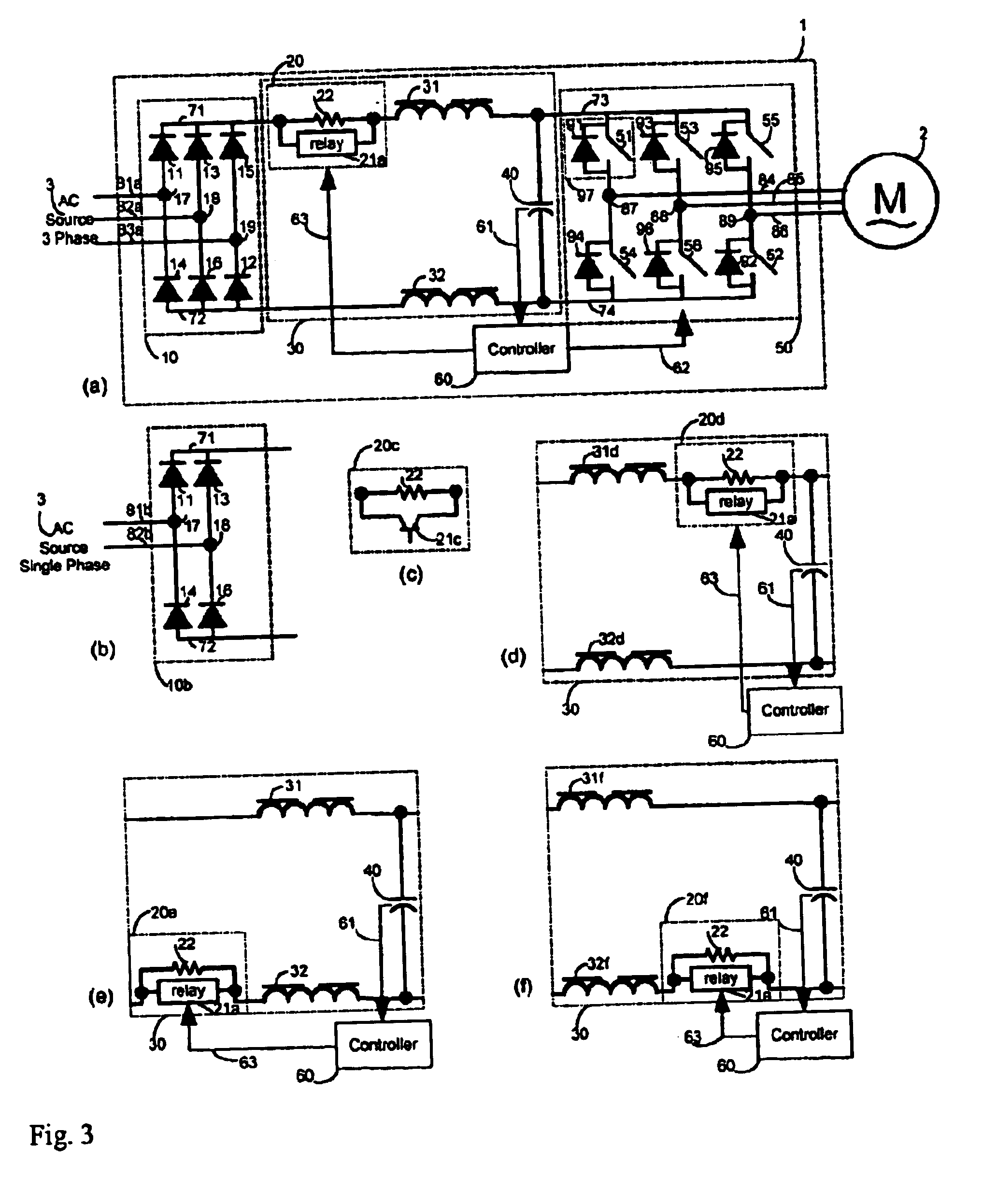
An AC / DC / AC power converter constructed according to the preferred embodiment of the present invention is indicated generally at 1 in FIG. 3a. A three-phase AC power source 3 supplies energy through wires 81, 82 and 83 to converter 1. Within converter 1, diodes 11-16 forms a unidirectional three-phase rectifier 10 only capable of passing the input energy from AC source 3 to the DC link 30, not vice versa. Cathodes of diodes 11, 13 and 15 are connected together to form a positive terminal 71. Anodes of diodes 14, 16 and 12 are tied similarly to form a negative terminal 72. Anode of diode 11 and cathode of diode 14 are connected together to wire 81 via node 17. Similarly anode of diode 13 and cathode of diode 16 joint to node 18 and connect to wire 82. Anode of diode 15 and cathode of diode 12 tie to node 19 and wire 83. Rectifier 10 rectifies ac voltage from AC source 3 and presents a voltage consisting of a DC average voltage plus multiples of 6.sup.th harmonics between positive and...


PUM


Abstract

An AC / DC / AC power converter is constructed without using any electrolytic capacitor, such that it is more compact, durable and reliable. This converter only required a small capacitance for its DC link and this capacitor can be easily obtainable with other types of capacitors such as film or ceramic type. The system further includes means to disconnect both input and output to this DC bus capacitor. A controller capable of fast monitoring the DC bus voltage is also able of quickly disconnecting the capacitor out of either input or output energy path to prevent the capacitor from being charged to over-voltage. The controller also possesses capability of re-connecting the disrupted energy path once the DC bus voltage returns to normal.

Description

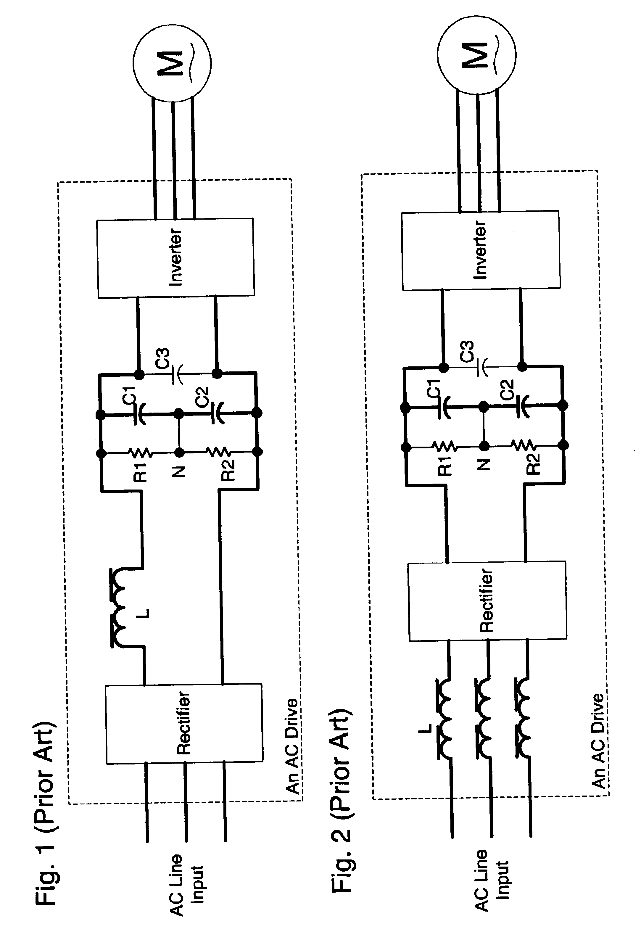
FEDERAL SPONSORED RESEARCH & DEVELOPMENTNot Applicable1. Technical Field of the InventionThe present invention relates generally to an alternate current to direct current and then back to alternate current (AC / DC / AC) power conversion system, and more particularly to an improved power structure coupled with a control means of an AC / DC / AC power conversion apparatus designed to convert fixed frequency AC source into variable frequency and variable voltage source for supplying power to an electric motor.2. Background ArtsFIGS. 1 and 2 show power structures of conventional AC / DC / AC power converter for driving an AC motor. The converter typically includes a rectifier, a DC link and an inverter. Majority of ac drives do not need to provide regenerative feature and hence a diode rectifying front end is cost effective and suffices as the rectifier. The rectifier directs the AC power from the ac lines to provide power with a DC plus a six times line frequency component as input to the DC link...

Claims


Application Information

Patent Timeline
IPC IPC(8): H02M5/458H02M5/00H02M1/00
CPCH02M5/458H02M1/32
Inventor ZHOU, DONGSHENG
Owner WICON
Learn More