Gasification reactor vessel

a gasification reactor and gasification technology, applied in the field of pressure vessels, can solve the problems of limited operating time to be achieved, long operating time, and use of ash-free fuel materials

Inactive Publication Date: 2004-12-07
NOELL KRC ENERGIE & UMWELTTECHN GMBH +1
View PDF13 Cites 16 Cited by
  • Summary
  • Abstract
  • Description
  • Claims
  • Application Information

AI Technical Summary

Benefits of technology

Another object of the invention is to provide a gasification reactor vessel with a cooling system for cooling the reactor vessel and an inwardly adjacent protective refractory layer with coolant supplied at a higher pressure than a pressure in the gasification chamber without imposing an undesirable or potentially damaging force of the coolant pressure on the refractory layer. A method for cooling the refractory layer and reactor vessel also provided.
As a result, the cooling system withstands and is unaffected by the maximum possible pressure difference that can exist between the reaction chamber and atmospheric pressure.
An advantage of the invention is that the pressure and temperature in the cooling channels can be selected in such a way that the cooling channels are operated above or below the coolant boiling point.

Problems solved by technology

However, they can only be used for ash-free fuel materials, since the liquid slag which flows off the inner surface of the reaction chamber during the entrained-bed gasification dissolves the refractory lining and therefore only allows very limited operating times to be achieved before an expensive refit is required.
Such systems are extremely robust and guarantee long operating times. A significant drawback of such systems consists in the fact that up to approx.
Various fuel and waste materials, such as for example heavy-metal- or light-ash-containing oils, tars or tar-oil solid slurries contain too little ash to form a sufficiently protective layer of slag with cooled reactor walls, resulting in additional energy losses, yet on the other hand the ash content is too high to prevent the refractory layer from melting away or being dissolved if reactors with a refractory lining were to be used and to allow sufficiently long operating times to be achieved before a refit is required.
A further drawback is the complicated structure of the reactor wall, which may lead to considerable problems during production and in operation.
The drawback is that only limited pressure differences between the reaction chamber and the cooling gap are possible, leading to a considerable outlay on control and safety engineering.
This may cause problems in the event of rapid depressurization of the reaction chamber for safety engineering reasons, since the pressure in the cooling gap cannot be adapted as quickly, and this may lead to mechanical destruction of the cooling shell.
However, this screen cannot be used to good effect if the ash contents in the fuel and waste materials differ.
As a result, the cooling system withstands and is unaffected by the maximum possible pressure difference that can exist between the reaction chamber and atmospheric pressure.

Method used


Image

  • Gasification reactor vessel
  • Gasification reactor vessel
  • Gasification reactor vessel

Examples


Embodiment Construction

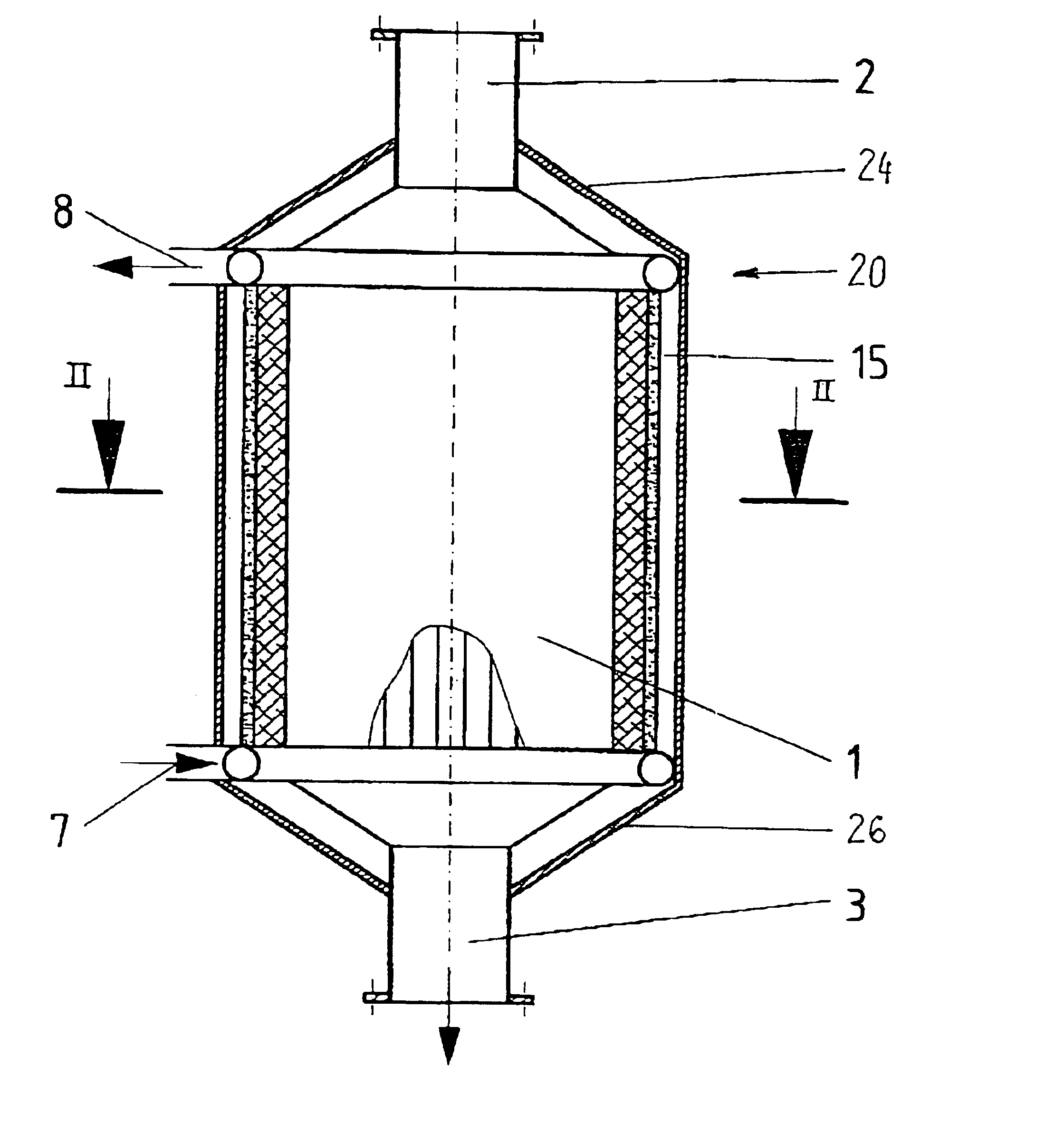
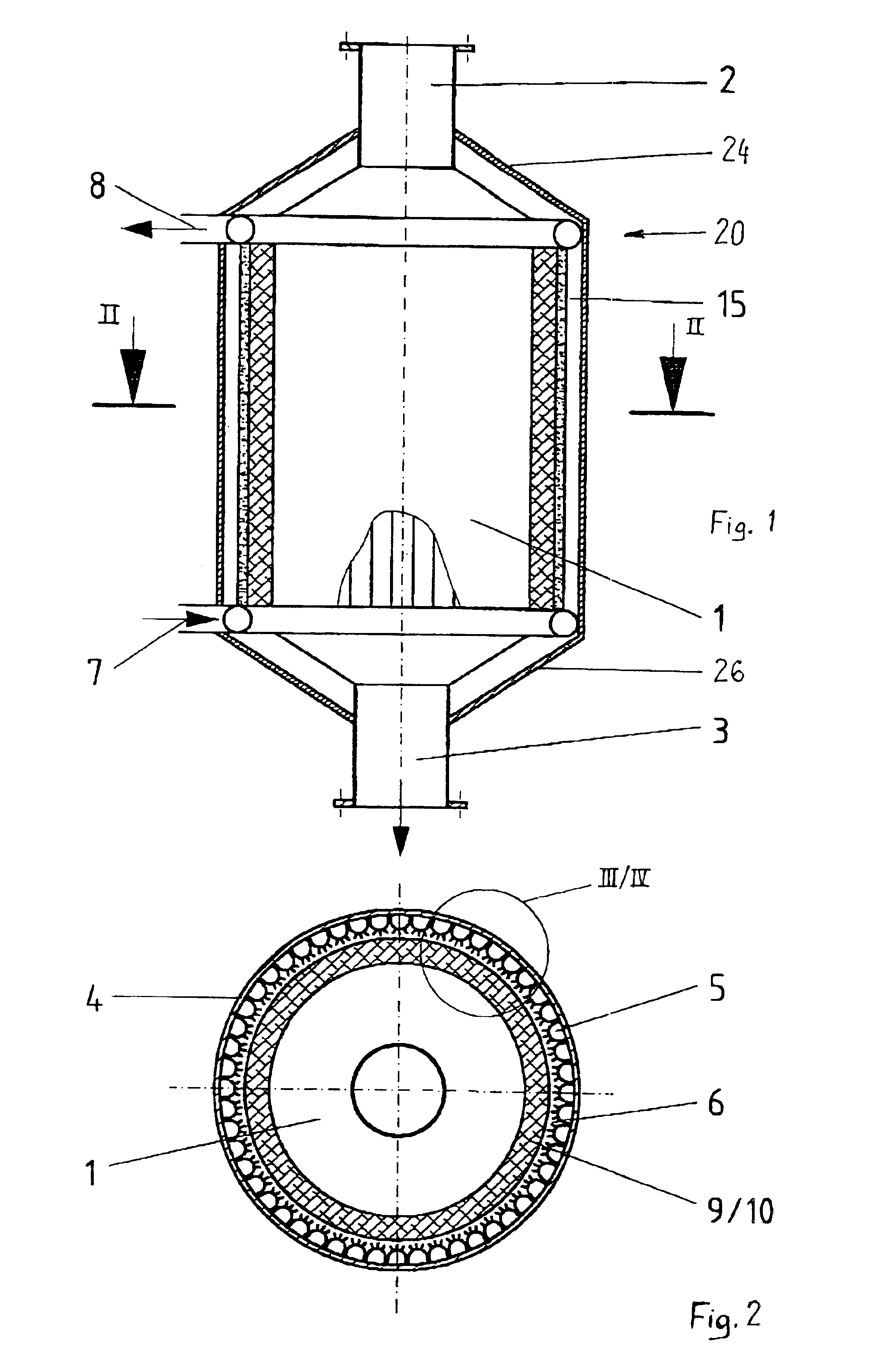
FIGS. 1 and 2 show a longitudinal section and a cross section through the gasification reactor. The conversion of the fuel, residual and waste materials using the oxygencontaining oxidizing agent to form a crude gas containing high levels of H.sub.2 and CO takes place in the reaction chamber 1.

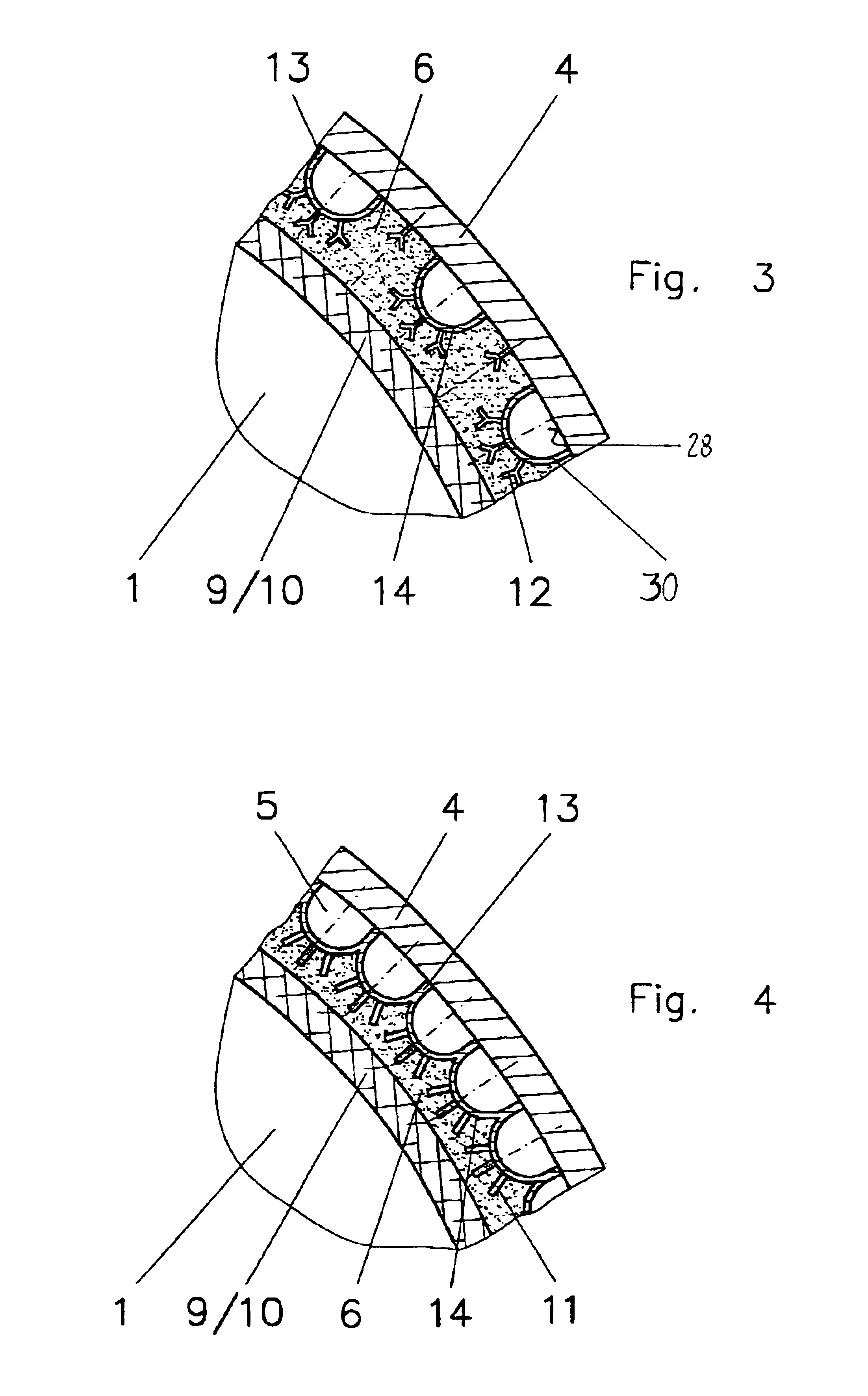
Referring to FIG. 1, the gasification reactor vessel 20 includes a cylindrical pressure shell 4 and shell ends 24, 26 at opposite ends of shell 20. The elongated encircling body wall of the shell has an inner side 28 (FIG. 3) around which is arrayed a plurality of channel members 30 which extend lengthwise in the shell with the channel open side facing the innerside 28. The channel members 30 are fixedly connected as by watertight and gastight welding connections to the inner side 28 so that an enclosed conduit space is defined in which water coolant can flow. The channel members 30 can be circularly arrayed inside the shell at spaced locations as shown in FIG. 3 or they may be in side-by-side...


PUM

PropertyMeasurementUnit
pressureaaaaaaaaaa
pressureaaaaaaaaaa
refractoryaaaaaaaaaa

Abstract

The invention relates to a reactor vessel and method for the gasification of carbon-containing fuel, residual and waste materials using an oxygen-containing oxidizing agent and in a reaction chamber which is designed as an entrained-bed reactor, at pressures between ambient pressure and 80 bar, preferably between ambient pressure and 30 bar, the contour of the reaction chamber being delimited by a cooling system, and the pressure in the cooling system always being held at a higher level than the pressure in the reaction chamber, and the cooling system withstanding the maximum possible pressure difference with respect to the reaction chamber, which has been depressurized to atmospheric pressure, which reactor vessel is distinguished by the fact that cooling channels are formed by webs which are in contact both with a refractory protective layer and with the pressure shell.

Description

1. Field of the InventionThe present invention relates to a pressure vessel wherein the gasification of fuel, residual and waste materials can be carried out in an entrained-bed type gasification reaction.2. Description of the Related ArtFuel, residual and waste materials are to be understood as meaning those with or without an ash content, such as brown or hard coals and their cokes, water / coal suspensions, but also oils, tars and slurries, as well as residues or wastes from chemical and wood pulping processes from the papermaking and pulp industry, such as for example black liquor from the Kraft process, as well as solid and liquid fractions from the waste management and recycling industry, such as used oils, PCB-containing oils, plastic and domestic refuse fractions or their processing products, and residual and waste materials from the chemical industry, such as for example nitrogen- and halogen-containing hydrocarbons or alkali metal salts of organic acids.The autothermal entra...

Claims


Application Information

Patent Timeline
Patent Type & Authority Patents(United States)
IPC IPC(8): C10J3/76C10J3/46C10J3/00C10J3/56D21C11/12
CPCC10J3/56C10J3/76D21C11/125F28F19/02C10J3/485F28D7/0041C10J2300/1223
Inventor SCHINGNITZ, MANFREDREUTHER, CHRISTIANDEGENKOLB, DIETMAR
Owner NOELL KRC ENERGIE & UMWELTTECHN GMBH
Why Eureka
Try Eureka