

Solar battery module and power generation apparatus
a solar battery and power generation technology, applied in the direction of batteries, light radiation electric generators, instruments, etc., can solve the problems of overcurrent in the the cost of the ac module will increase, and the current in the connector or current path of the ac module to exceed the rated current, so as to prevent overcurrent flow in the solar battery module
- Summary
- Abstract
- Description
- Claims
- Application Information
AI Technical Summary
Benefits of technology
Problems solved by technology
Method used
Image

Examples
first embodiment
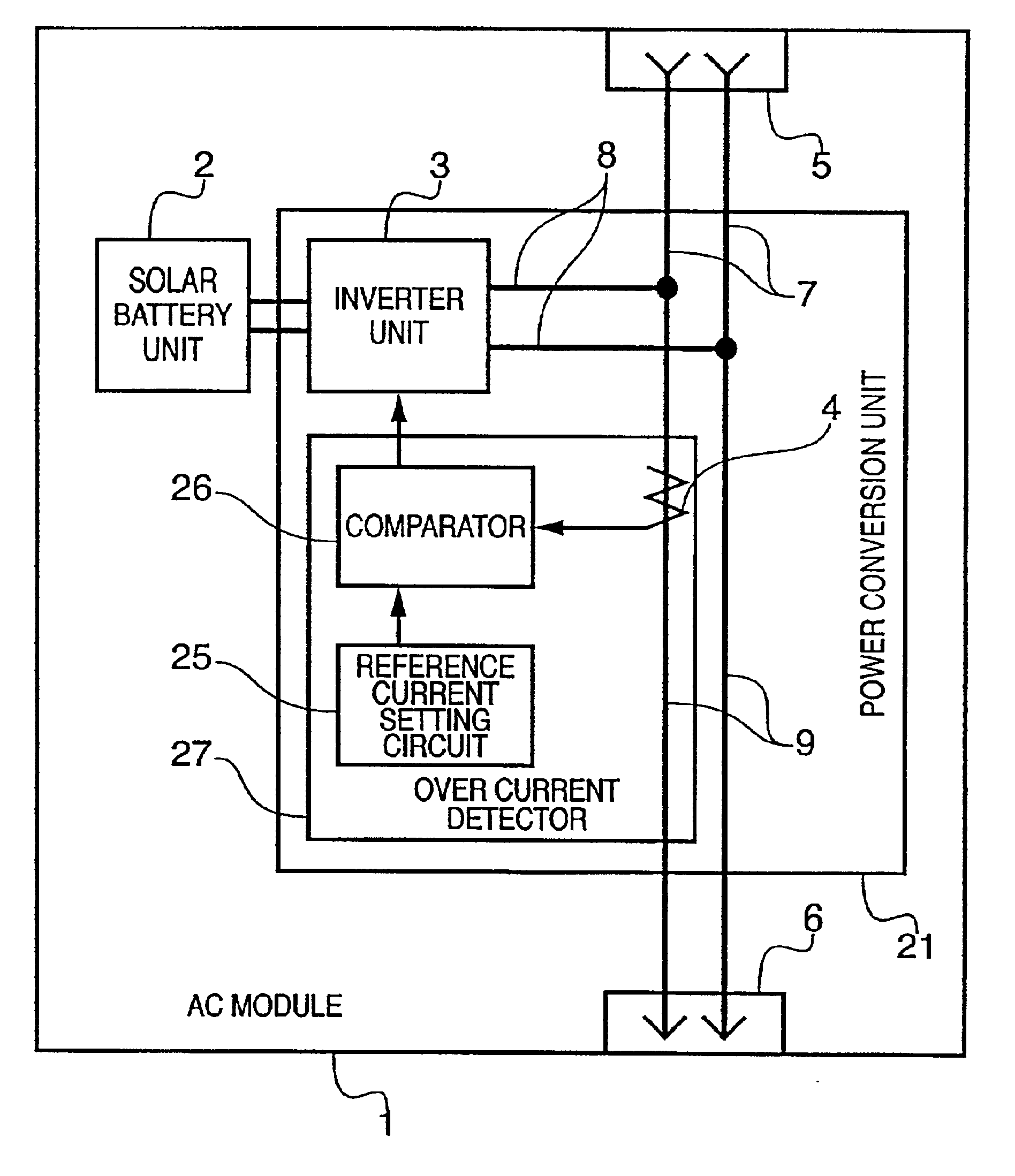
[0032]As shown in FIG. 4, the solar battery unit 2 accounts for the most part of the AC module 1. Preferably used as the solar battery unit 2 is one employing amorphous silicon, or polycrystalline silicon or crystalline silicon in its photoelectronic transducer. DC power is outputted from an electrode (not shown) of the solar battery unit 2. Note when the insolation is 1 kW / m2, the rated output of the solar battery unit 2 in the first embodiment is: the rated voltage, 25V; rated current, 4 A; and rated power, 100 W.
[0033]Power Conversion Unit
[0034]The power conversion unit 21 comprises an inverter unit 3, an over current detector 27, and current paths 7, 8 and 9. The power conversion unit 21 converts DC power supplied from the solar battery unit 2 to 50 / 60 Hz and 100V AC power. The converted AC power is collected together with AC power, which is inputted from an input connector 5, and then outputted to an output connector 6. Note in the first embodiment, the power conversion unit 21...
second embodiment
[0062]FIG. 7 is a block diagram showing a construction of the AC module 1 according to the In place of the comparator 26 shown in the construction of the AC module 1 in FIG. 3, a subtracter 54 is provided.
[0063]The subtracter 54 subtracts the set value of the reference current setting circuit 25 from the output of the current detector 4. When the obtained result is positive, the obtained value is outputted, but when the result is negative, zero is outputted as an output reduction signal.
[0064]The control circuit 17 computes the aforementioned current command value signal, AC current value 15, and output reduction signal which is inputted from the subtracter 54 through the signal input terminal 20 to generate a current error signal. As mentioned above, the gate control circuit, which receives the current error signal, compares the current error signal with the reference triangular wave signal which is about 20 kHz, and generates the PWM switching control signal to be supplied to the...
third embodiment
[0075]Unlike the AC module 1 shown in FIGS. 3 and 7, the input connector 51 and output connector 61 of the AC module 1 are three-pole connectors. The current detector 4 is arranged in the phase where power of a collective-power current path 91 is collected, i.e., the phase to which the inverter unit 3 is connected.
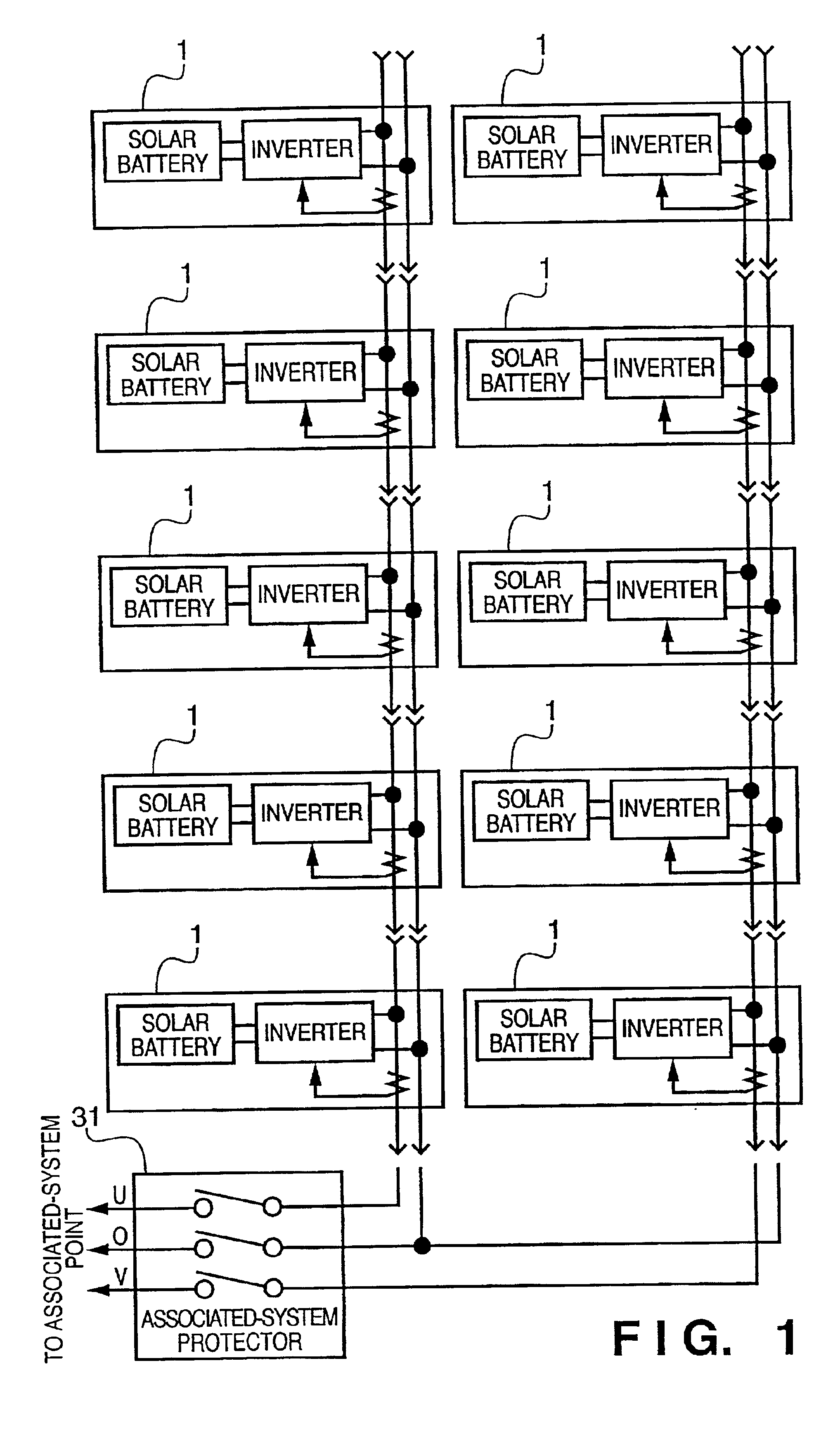
[0076]FIG. 11 is a block diagram showing a construction of a photovoltaic power generation apparatus where the AC modules 1 shown in FIGS. 9 and 10 are alternately connected. Five of the AC module 1 shown in FIG. 9 are connected to U phase and five of the AC module 1 shown in FIG. 10 are connected to V phase.
[0077]The construction shown in FIG. 11 can also prevent over current flow in the collective-power current path 91 and output connector 61.
[0078]
[0079]Each of the above-described embodiments is applicable not only to a system-association type photovoltaic power generation apparatus, but also to a photovoltaic power generation apparatus which supplies AC power to a loa...
PUM
 Abstract
Description
Claims
Application Information