Method and apparatus for charged particle beam microscopy

a charge particle and beam microscopy technology, applied in material analysis using wave/particle radiation, instruments, nuclear engineering, etc., can solve the problems of inability to obtain alignment analysis accuracy, low-s/n image, and difficulty in applying image processing including image binarization to a low-s/n image,

Inactive Publication Date: 2005-01-04
HITACHI LTD
View PDF11 Cites 60 Cited by
  • Summary
  • Abstract
  • Description
  • Claims
  • Application Information

AI Technical Summary

Benefits of technology

For analysis of axial displacement, an analysis method using phase difference of Fourier transform images is applied to displacement analysis between images before and after an objective lens current is varied. This displacement analysis method can analyze even low-contrast images. It can be assumed that there is only a δ peak in a position corresponding to a positional displacement in an processed image obtained by inverse Fourier transform of a phase difference image between Fourier transform images of the respective images. Accordingly, the po...

Problems solved by technology

It is difficult to apply image processing including image binarization to a low-S/N, that is, low-contrast image.
In addition, geometrical analysis is easily affected by image deformation caused by a focal variation, so that satisfactory displacement analysis accuracy, that is, alignment analysis accuracy cannot be obtained.
Even if analytic impossibility has been caused by image deterioration, an incorrect analytic result is outputted as it is.
For example, if a displacement from an optical axis is too large, a specimen may get out of a field of view due to a focal variation so as to cause impossibility of displacement analysis.
In addition, if a focal variation is too large, an image may be indistinct enough to cause impossibility of displacement analysis.
In the au...

Method used


Image

  • Method and apparatus for charged particle beam microscopy
  • Method and apparatus for charged particle beam microscopy
  • Method and apparatus for charged particle beam microscopy

Examples


embodiment 1

(Embodiment 1)

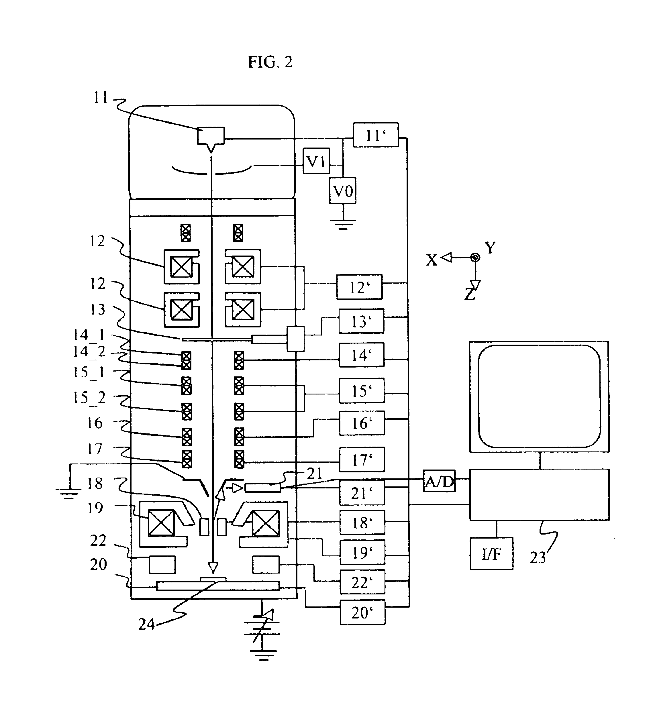
FIG. 2 is a view showing a basic configuration of a scanning electron microscope for use in an embodiment of the present invention. The scanning electron microscope is constituted by an electron gun 11 and a control circuit 11′ for controlling a primary electron beam acceleration voltage or an extraction voltage; condenser lenses 12 and a control unit12′ for controlling current values thereof; an objective aperture 13 and a control unit 13′ for controlling the hole position of the objective aperture; stigmators 14_1 and 14_2, and a control unit 14′ for controlling current values thereof; alignment deflectors 15_1 and 15_2 for the respective stigmators, and a control unit 15′ for controlling voltage values or current values thereof; an alignment deflector 16 for condenser lens, and a control unit 16′ for controlling a voltage value thereof; a scanning deflector 17 and a control unit 17′ for controlling a voltage value or a current value thereof; an E×B deflector 18 and ...

embodiment 2

(Embodiment 2)

In Embodiment 2, description will be made about a circuit pattern inspection apparatus having an automatic adjustment unit shown in Embodiment 1. FIG. 22 shows a configuration of the circuit pattern inspection apparatus used in Embodiment 2. The circuit pattern inspection apparatus has an inspection chamber 102 the inside of which is vacuum-pumped, and a spare chamber (not shown in this embodiment) for carrying a specimen substrate 109 into the inspection chamber 102. This spare chamber can be vacuum-pumped independently of the inspection chamber 102. In addition, the circuit pattern inspection apparatus is constituted by a control unit 106 and an image processing unit 105 as well as the inspection chamber 102 and the spare chamber. The inside of the inspection chamber 102 is roughly constituted by an electron beam optics 103, a secondary electron detector 107, a specimen chamber 108, and an optical microscope unit 104. The optical microscope unit 104 is disposed near ...

embodiment 3

(Embodiment 3)

FIG. 26 is a view showing a whole configuration of an apparatus in which a focused ion beam irradiation column and a scanning electron microscope column have been combined. This apparatus is chiefly constituted by a focused ion beam irradiation column 381 having an ion source 351, a lens 352 for focusing an ion beam emitted from the ion source 351, a deflector 353, a deflector 373 for correction, an objective lens 371, and so on; a scanning electron microscope column 382 having an electron gun 357, a lens 359 for focusing an electron beam 358 emitted from the electron gun 357, a deflector 360, a deflector 374 for correction, an objective lens 372, and so on; and a vacuum specimen chamber. In addition, this apparatus has a secondary particle detector 356 for irradiating a specimen 361 with a focused ion beam (FIB) 354 to thereby detect secondary electrons or secondary ions from the specimen, a movable specimen base 362 for mounting the specimen 361 thereon, and a specim...


PUM


Abstract

By use of charged particle beam images picked up in different conditions, a positional displacement caused by parallax is analyzed, and an optics of an apparatus for charged particle beam microscopy is corrected automatically. An analysis method using phase difference of Fourier transform images and having analytic accuracy lower than that for one pixel is adopted for the displacement analysis. In addition, a degree of coincidence between images calculated in this analysis method is used as a criterion for evaluating the reliability of an analysis result. Since the analysis method based on parallax is low in specimen dependency, the operation range is expanded. In addition, by adopting a high-accuracy displacement analysis method, the apparatus correction accuracy is improved by one digit. A malfunction preventing flow is added using the degree of coincidence as a judgement criterion. Thus, the apparatus can deal with unmanned operation. In addition, the degree of coincidence can be used as a monitor of inspection states or a record of states in an inspection apparatus.

Description

BACKGROUND OF THE INVENTIONThe present invention relates to an apparatus for automatically adjusting an optics of an apparatus for charged particle beam microscopy.As for automatic correction of an optics of an apparatus for charged particle beam microscopy, there are three known examples as follows. A known example 1 is an automatic alignment unit for a scanning electron microscope disclosed in JP-A-10-92354. In order to adjust a primary electron beam to pass through the center of an objective lens, images before and after varying an exciting current for the objective lens are acquired respectively. After the acquired images are binarized, the displacement direction and the displacement distance of the image caused by misalignment are calculated. An alignment unit is controlled so that the displacement distance vanishes. A known example 2 is an automatic focus corrector for a scanning electron microscope disclosed in JP-A-7-176285. The focused state of a primary charged particle be...

Claims


Application Information

Patent Timeline
IPC IPC(8): H01J37/28H01J37/22H01J37/04G01Q30/04H01J37/153H01J37/21
CPCH01J37/21H01J37/226H01J37/28H01J2237/31749H01J2237/216H01J2237/2482H01J2237/31745H01J2237/1501
Inventor TSUNETA, RURIKOKOGUCHI, MASANARINOZOE, MARIFUKUDA, MUNEYUKISATO, MITSUGU
Owner HITACHI LTD
Why Eureka
Try Eureka