

Laser interferometer displacement measuring system, exposure apparatus, and electron beam lithography apparatus
a technology of displacement measurement and displacement measurement, applied in the field of displacement measurement technique, can solve the problem that prior-art noise processing by averaging cannot provide a sufficient absolute accuracy, and achieve the effect of increasing accuracy
- Summary
- Abstract
- Description
- Claims
- Application Information
AI Technical Summary
Benefits of technology
Problems solved by technology
Method used
Image

Examples
embodiment 1
[Embodiment 1] Basic Configuration of a Laser Interferometer Displacement Measuring System with a Distortion Correction Function
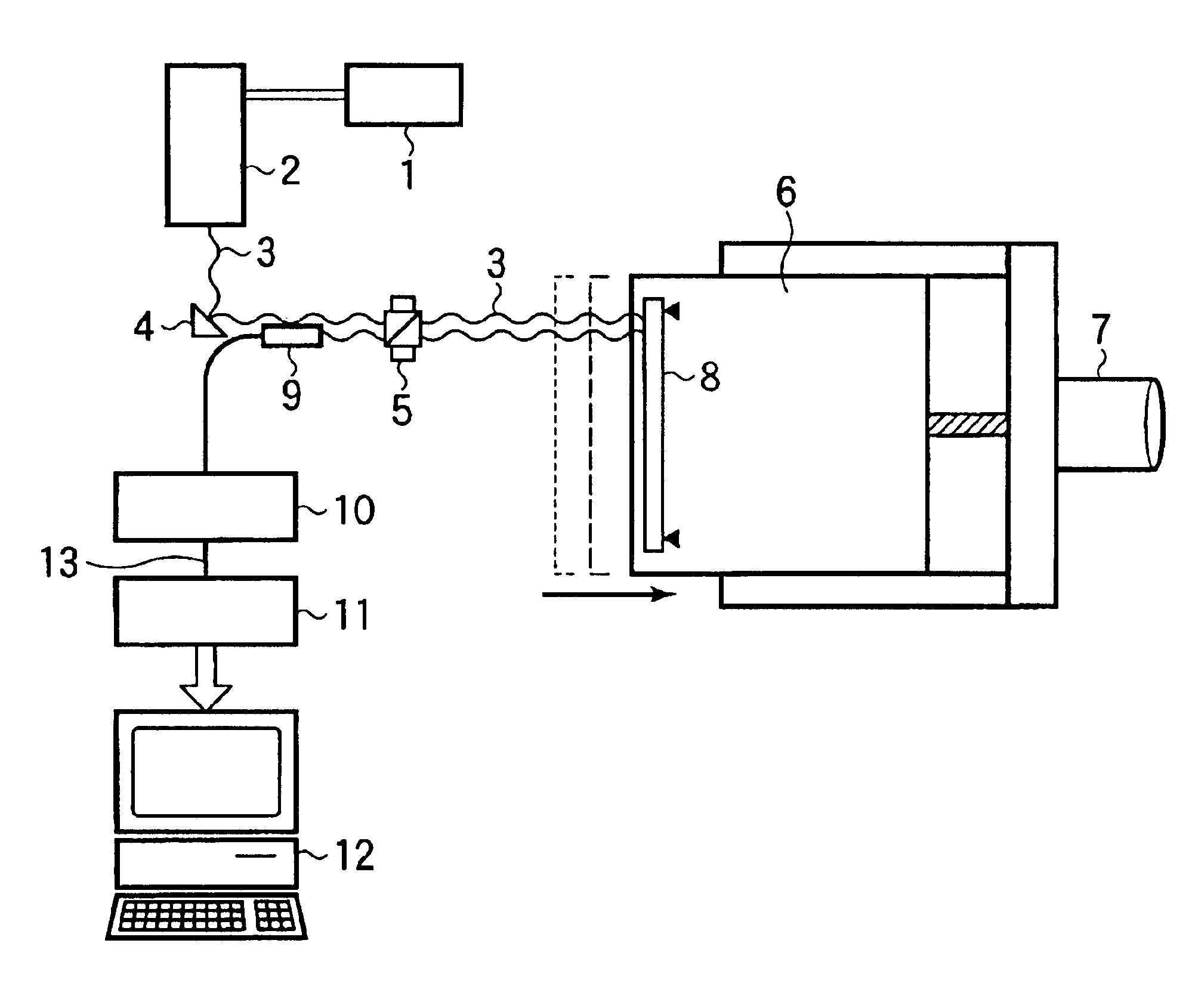
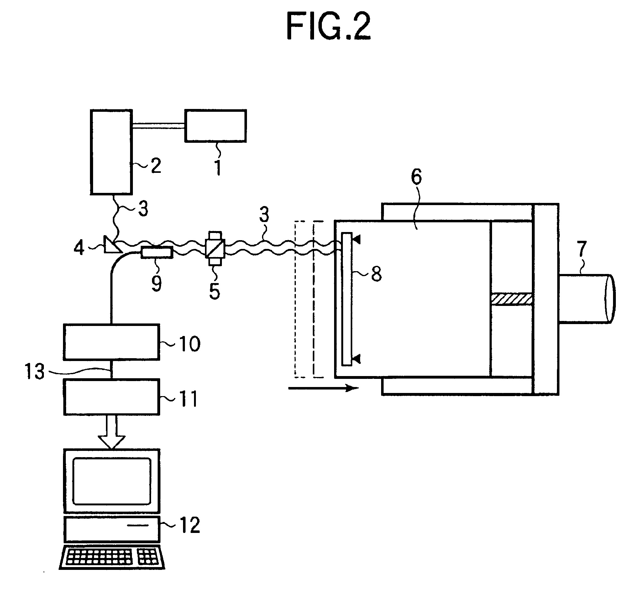
The overall exemplary configuration of a laser interferometer displacement measuring system according to the present invention is shown in FIG. 2. In the figure, shown is an actual example in which laser displacement measurement is employed for measuring a single-axis stage with accuracy and performing feedback control. The single-axis stage has a motor or the like as a stage driving power source 7 and detects the distance of a movable stage table 6 using variations in position of a reflector 8 on the stage table.
A laser power supply 1 drives a gas laser light source 2 to generate laser light 3, which is in turn reflected on a beam bender 4 and then introduced into an interferometer 5. The optical path is divided into two paths inside the interferometer 5. One of the optical paths is the measurement path in which the light reaches the reflector 8 on the sta...
embodiment 2
[Embodiment 2] Configuration of Automatic Phase Tracking Means for Increasing Accuracy
FIG. 7 shows an exemplary configuration of automatic amplitude tracking distortion correction means which performs feedback control on the phase of cyclic function of a correction value to correct the distortion error of a wave cycle.
The measurement value 13 obtained by the measuring board is captured and then subtracted by the value that has passed through the parabolic component extracting filter 25, thereby providing a distortion error signal 26. This calculation method is the same as that described in Embodiment 1 using the determinant. In addition, the phase shifting value 17 is added to the measurement value 13 in the phase adder 16 to generate the table reference address 18. This value is employed as the input to the memory device 19 for a generating cyclic function value and to a cyclic orthogonal function table 36 having a phase orthogonal to the cyclic function. Incidentally, the memory d...
embodiment 3
[Embodiment 3] Configuration of Automatic Amplitude Tracking Distortion Corrector Means (1)
FIG. 10 shows an exemplary configuration of automatic amplitude tracking distortion corrector means for correcting the distortion error of a measurement value by automatically controlling the amplitude of two cyclic functions.
The measurement value 13 provided by the measuring board is captured and then subtracted by the value that has passed through the parabolic component extracting filter 25 to thereby provide the distortion error signal 26. This calculation method is the same as that described in Embodiment 2. On the other hand, the measurement value 13 is employed as it is to be inputted to the memory device 19 having the two cyclic functions therein and to the cyclic orthogonal function table 36. Each of the generated cyclic function value 30 and the cyclic orthogonal function value 37 is multiplied by the cyclic orthogonal function table 36 at each of the multipliers 31, 38, thereby prov...
PUM
 Abstract
Description
Claims
Application Information