Optical near-field generating element and optical apparatus including the same

Inactive Publication Date: 2005-01-04
PIONEER CORP
View PDF14 Cites 28 Cited by
  • Summary
  • Abstract
  • Description
  • Claims
  • Application Information

AI Technical Summary

Benefits of technology

The present invention is proposed in view of the above mentioned problems. It is therefore an object of the present invention to provide an optical near-field generating element that can incr

Problems solved by technology

Typically, since the light is diffracted, it is said that the treatment of a substance smaller than the wavelength of the light is substantially impossible in principle.
In view of this diffraction limit, it is already difficult to make the record density dramatically higher in the optical memory.
Similarly, in view of the diffraction limit, even in a case of an optical microscope, it is already difficult to improve a resolution in an optical system using a usual lens.
In a case of an optically fine machining apparatus, an optical communication system, an optical device or various other optical apparatus, it is already difficult to attain a dramatically high performance.
However, if the optical near-field is generated, the strength of the light that can be used as the optical near-field on the output side is extremely low as compared with th

Method used


Image

  • Optical near-field generating element and optical apparatus including the same
  • Optical near-field generating element and optical apparatus including the same
  • Optical near-field generating element and optical apparatus including the same

Examples


first embodiment

(First Embodiment)

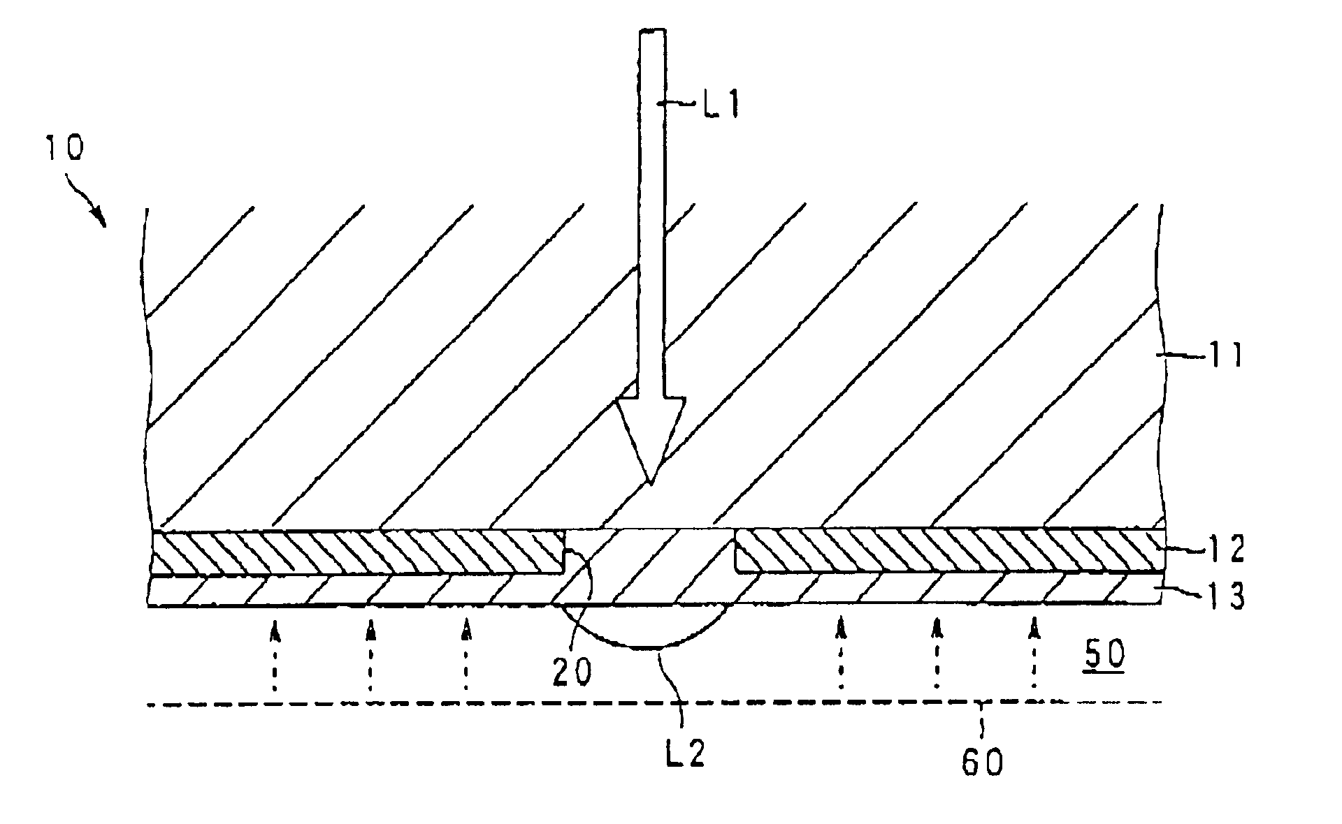
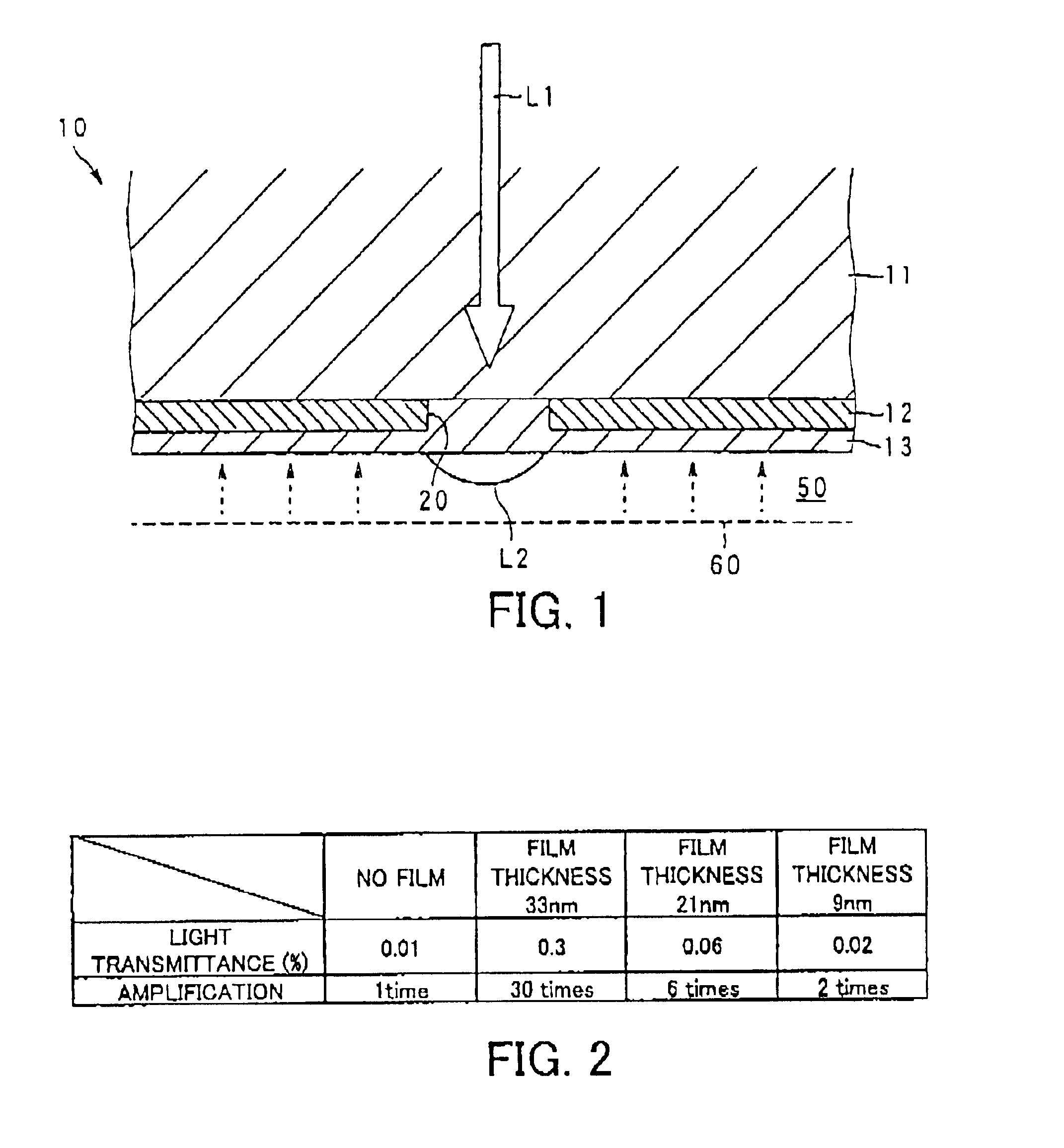
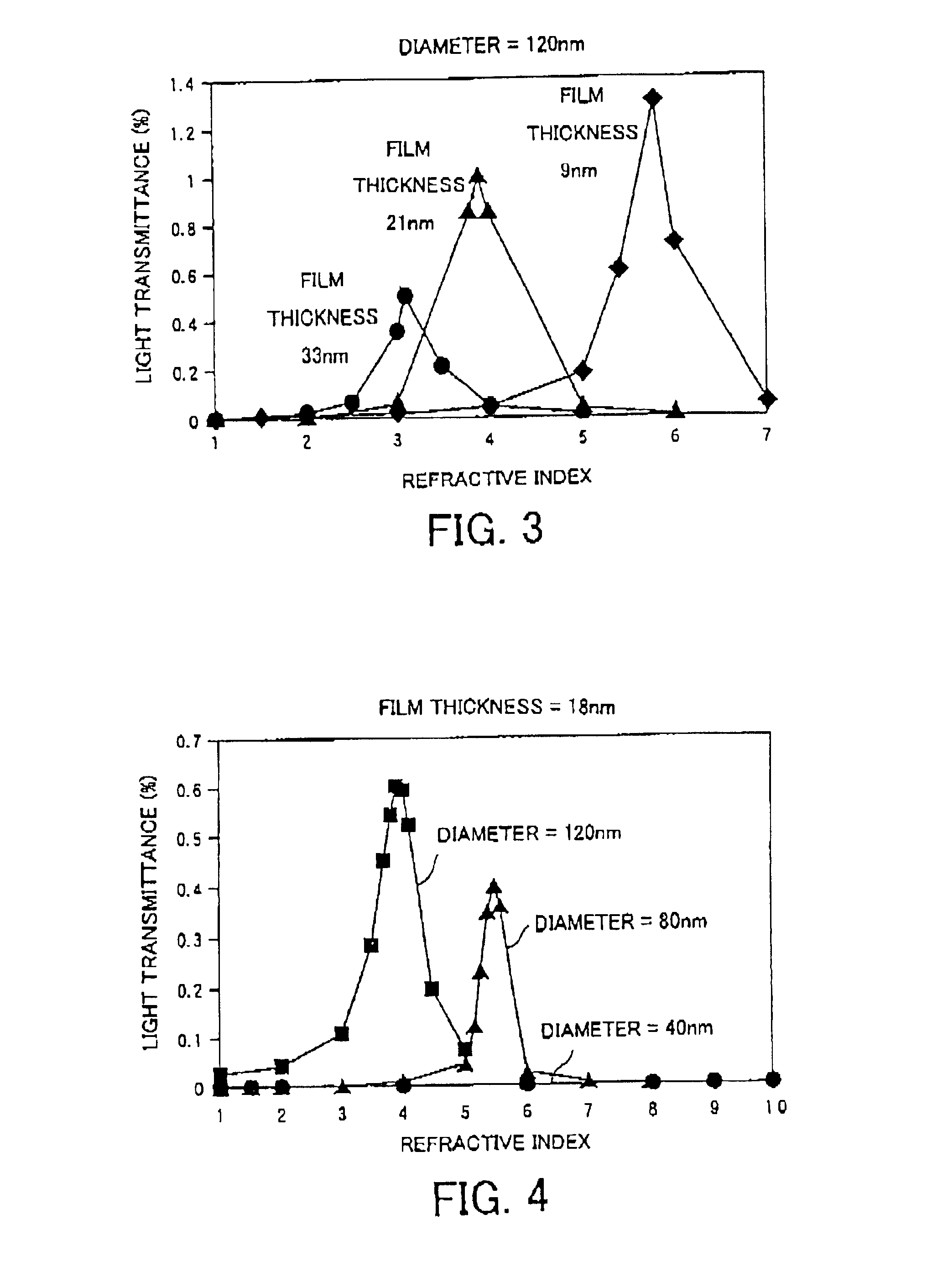
At first, an optical near-field generating element of a first embodiment is described with reference to FIGS. 1 to 4. FIG. 1 is an enlarged sectional view showing a portion near a micro opening of the optical near-field generating element according to the first embodiment of the present invention. FIG. 2 is a table showing a light transmittance and an optical amplification effect on the basis of a film thickness of a dielectric film adhered on the micro opening, which is obtained from a simulation. FIG. 3 is a property graph showing a relation between a refractive index and a light transmittance, with regard to various film thicknesses of the dielectric film when a diameter of the micro opening is fixed to 120 nm, which is obtained from the simulation. And, FIG. 4 is a property graph showing a relation between a refractive index and a light transmittance of a dielectric film, with regard to various diameters when a film thickness of the dielectric film is fixed to ...

second embodiment

(Second Embodiment)

An optical near-field generating element in a second embodiment will be described below with reference to FIGS. 5 to 8C. FIG. 5 is an enlarged sectional view showing a portion near a micro opening of the optical near-field generating element according to the second embodiment of the present invention. FIGS. 6A to 6D and FIGS. 7A to 7D are plan views of micro openings respectively showing various actual examples according to the shape of the micro opening in the second embodiment. FIGS. 8A to 8C are property graphs showing a secondary distribution of an optical strength of an optical near-field near the micro opening, which is obtained from a simulation.

As shown in FIG. 5, an optical near-field generating element 10′ in this embodiment is provided with: the light guiding member 11 for guiding the light L1 outputted from the light source; and a light shielding member 12′, which is placed on an optical path of the light L1 in the light guiding member 11, for defining...

third embodiment

(Third Embodiment)

An optical near-field generating element in a third embodiment will be described below with reference to FIG. 1 and FIGS. 6A to 7D.

The optical near-field generating element in the third embodiment is designed such that the shape of the micro opening 20 in the configuration of the first embodiment shown in FIG. 1 is replaced with the micro opening 20′ whose shape is modified by using the protrusion portion 31, such as the second embodiment shown in FIGS. 6A to 7D. The other configurations of the optical near-field generating element in the third embodiment are similar to those of the first embodiment.

Thus, according to the third embodiment, the protrusion portion formed on the light shielding member for defining the micro opening enables the existence region of the optical near-field to be made smaller, and also enables the optical strength to be made higher. At the same time, the dielectric film adhered on the micro opening enables the optical strength to be made m...


PUM


Abstract

An optical near-field generating element is provided with: a light shielding member, which is placed on an optical path of light emitted from a light source, for defining a micro opening having a diameter equal to or shorter than a wavelength of the light; and a dielectric film placed in close contact with the micro opening. Alternatively, an optical near-field generating element is provided with a light shielding member, which is placed on an optical path of lights emitted from a light source, for defining a micro opening having a diameter equal to or shorter than a wavelength of the light, the shielding member equipped with: a main portion for defining a basic shape of the micro opening; and a protrusion portion protruding from the main portion toward the center of the micro opening.

Description

BACKGROUND OF THE INVENTION1. Field of the InventionThe present invention relates to an optical near-field generating element, which is preferably used for an optical head or a probe array head of an optical memory, a fiber probe for a microscope, an exposing head in a fine machining apparatus containing an exposing apparatus and the like, and various optical apparatuses including them.2. Description of the Related ArtThe light emitted from an optical head used for an optical memory, such as a recordable optical disc and the like, needs to be basically fine focused in order to make a record density higher. For this reason, conventionally, instead of red laser light, blue laser light having a shorter wavelength is used, and a focus performance in a lens, such as a solid immersion lens and the like, is improved. Typically, since the light is diffracted, it is said that the treatment of a substance smaller than the wavelength of the light is substantially impossible in principle. The m...

Claims


Application Information

Patent Timeline
IPC IPC(8): G12B21/06G11B7/125G12B21/00G11B7/135G01Q60/18G01Q60/22G01Q70/06
CPCB82Y20/00B82Y35/00G11B7/1398G11B7/1381G11B7/1384G11B7/1387G01Q60/22B82Y10/00
Inventor SUGIURA, SATOSHIYAMAKAWA, YUZO
Owner PIONEER CORP
Why Eureka
Try Eureka