Probe tip thermal isolation and fast prediction algorithm

a technology of thermal isolation and prediction algorithm, applied in the field of electronic thermometers, can solve problems such as slow or inaccurate temperature readings, and achieve the effects of reducing many of these inaccuracies, reducing response time, and optimizing feedback algorithm

Inactive Publication Date: 2005-01-04
CARDINAL HEALTH IRELAND UNLTD
View PDF50 Cites 107 Cited by
  • Summary
  • Abstract
  • Description
  • Claims
  • Application Information

AI Technical Summary

Benefits of technology

The present invention is embodied in a prediction type electronic thermometer configured to thermally decouple the thermometer probe tip from the thermometer shaft. Advantages included in the present invention provide active feedback control to a heater element in the thermometer shaft which heats the shaft in response to signals from temperature sensors according to a time optimized algorithm. According to the present invention, a thermal isolator isolates or thermally decouples the shaft from the tip. Heat from the patient flows to the tip and remains there raising the tip temperature more quickly than raising the tip and thermally coupled shaft. Equilibrium between the temperature sensor and the patient is thereby reached more quickly. A close fitting probe cover having nominal resistance thermally isolates the tip from the patient when the probe is placed into a patient cavity. Thermal energy flows from the patient tissue through the cover and into the tip.
A heater control component uses an active feedback control algorithm according to the present invention to track the probe tip temperature as indicated by the signal from the temperature sensors. The heater control component increases current flow to the heater in increments that are calculated to minimize the time required for the patient thermal energy to raise the tip temperature.
The thermometer disclosed by West introduces inaccuracies to temperature measurements due to the heat that is transferred to the tip sensor elements from the heater element rather than from the patient being measured. A thermal isolator that is used in embodiments of the present invention reduces many of these inaccuracies. Further inaccuracies and inefficiencies in the West thermometer are caused by the analog feedback method of heater control which is not mathematically optimized to the most time efficient method of adding heat to the probe tip. Embodiments of the present invention overcome these inaccuracies by using digital feedback to implement an optimized feedback algorithm. Still further disadvantages of the analog feedback circuitry of the West device include the required careful tuning of resistor elements in the feedback circuit and inaccuracies introduced by the manufacturing differences between the resistive elements and the feedback circuit. Embodiments of the present invention do not require such tuning of components. The West device also disadvantageously waits until thermal equilibrium in the tip is reached which may take approximately 26 seconds. The present invention provides a significant decrease in response time by more rapidly predicting an equilibrium temperature according to early sensor measurements.
The present invention features a probe tip that is thermally decoupled from the probe shaft thereby substantially reducing response time of the temperature sensing element in the probe tip. Thermal energy from the heater element does not flow readily into the probe tip so the temperature sensing element in the probe tip can provide a more accurate representation of the patient temperature.
Further features of the present invention include a heater control circuit which does not require tuning of a plurality of resisters or other electronic components and does not suffer from inaccuracies attributable to manufacturing tolerance differences in said plurality of electronic components such as resisters and capacitors and further does not suffer from the inaccuracies introduced by heating the probe tip.
Embodiments of the present invention also feature the use of calibration values that are read to compensate for thermistor variation instead of compensating for thermistor variation with added resistors. Labor intensive calibration steps are eliminated during manufacturing by eliminating the need for adding compensating resistors Further features of the embodiments of the present invention include a flex circuit that is used to maintain the geometric placement of components. The flex circuit reduces manufacturing costs for placement and connections of the temperature sensors and heater elements and their connections to the control and prediction circuitry.

Problems solved by technology

Such uncontrolled shaft heating may heat the probe shaft too slowly or too quickly and may cause slow or inaccurate temperature readings.

Method used


Image

  • Probe tip thermal isolation and fast prediction algorithm
  • Probe tip thermal isolation and fast prediction algorithm
  • Probe tip thermal isolation and fast prediction algorithm

Examples


Embodiment Construction

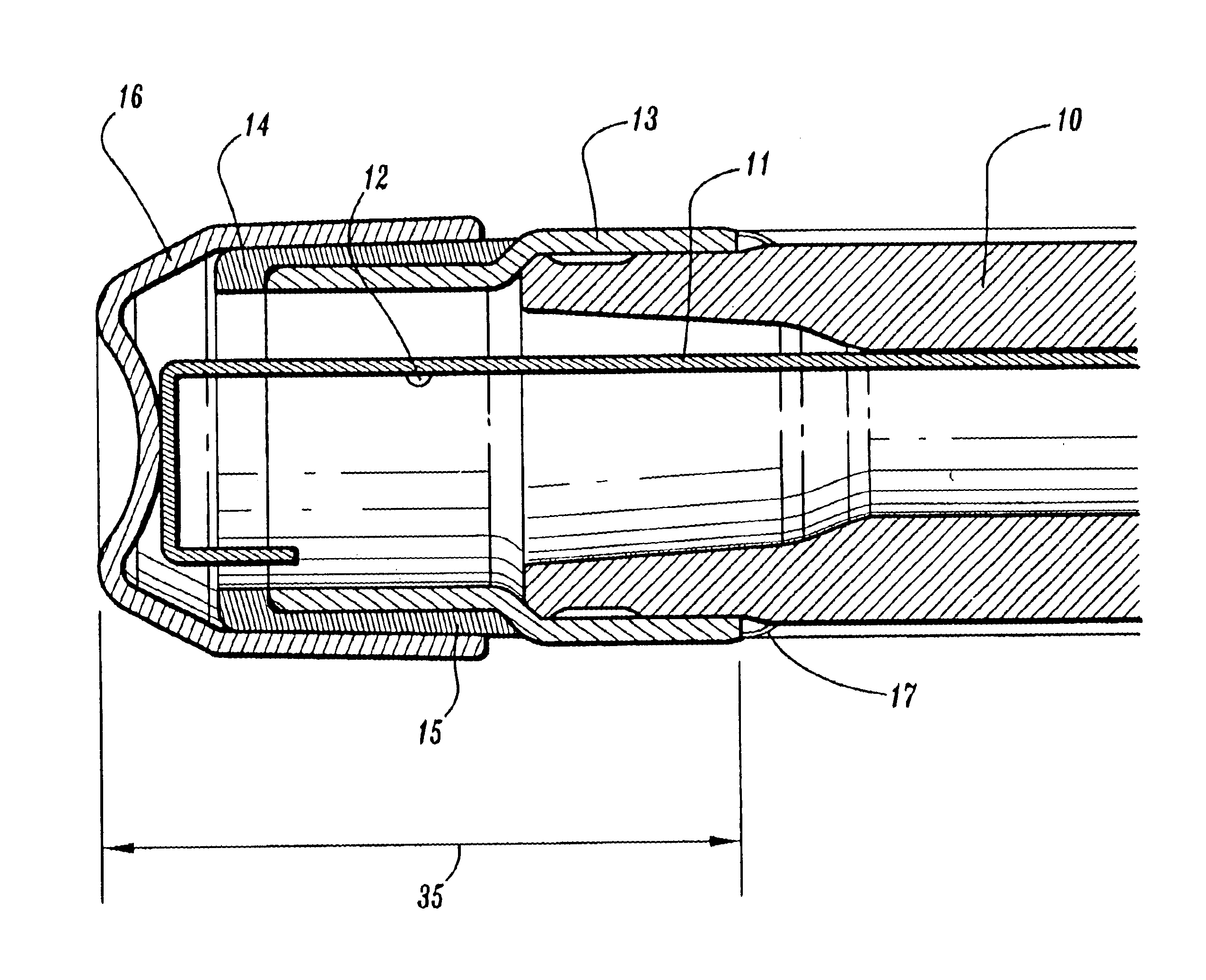
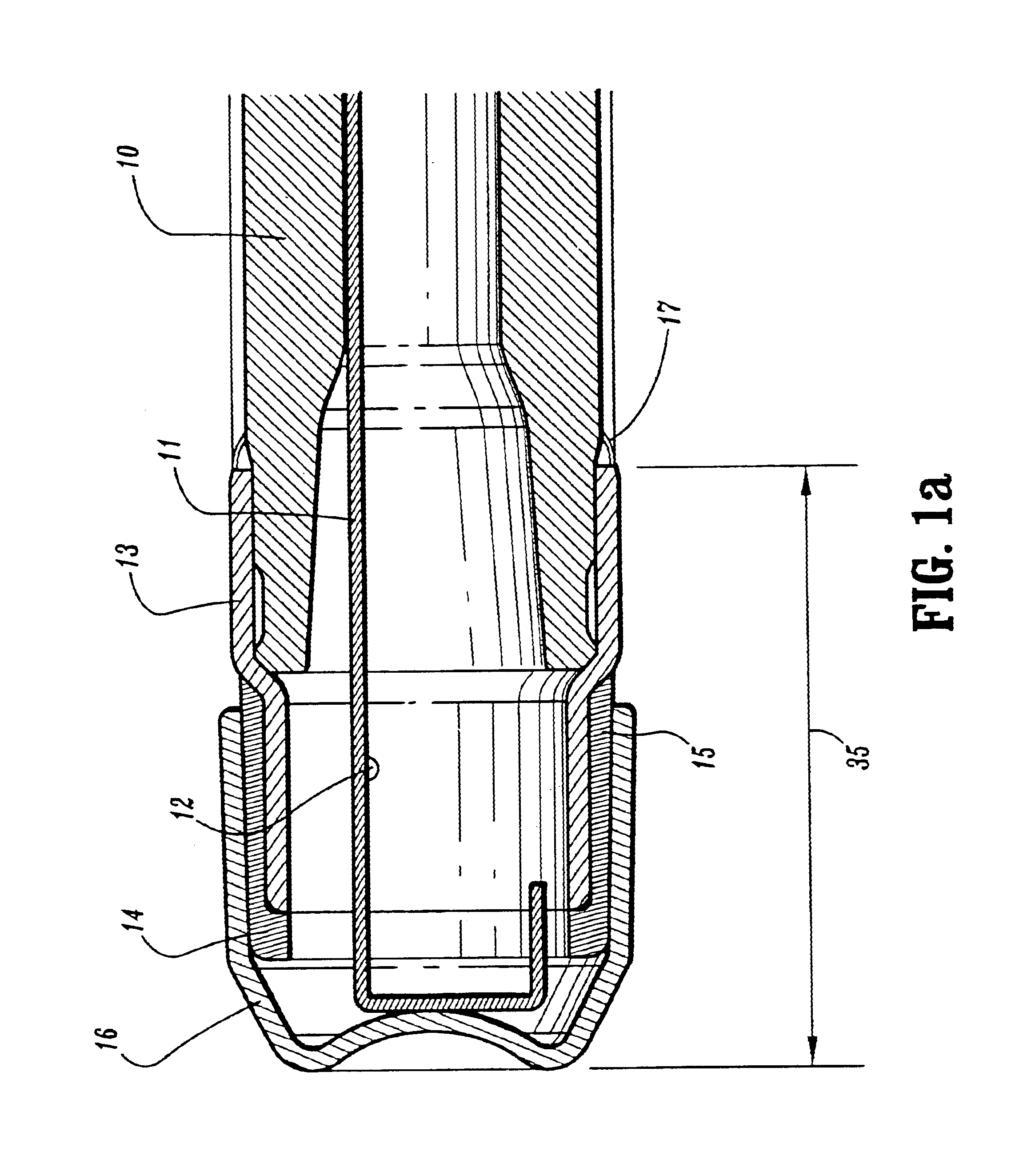
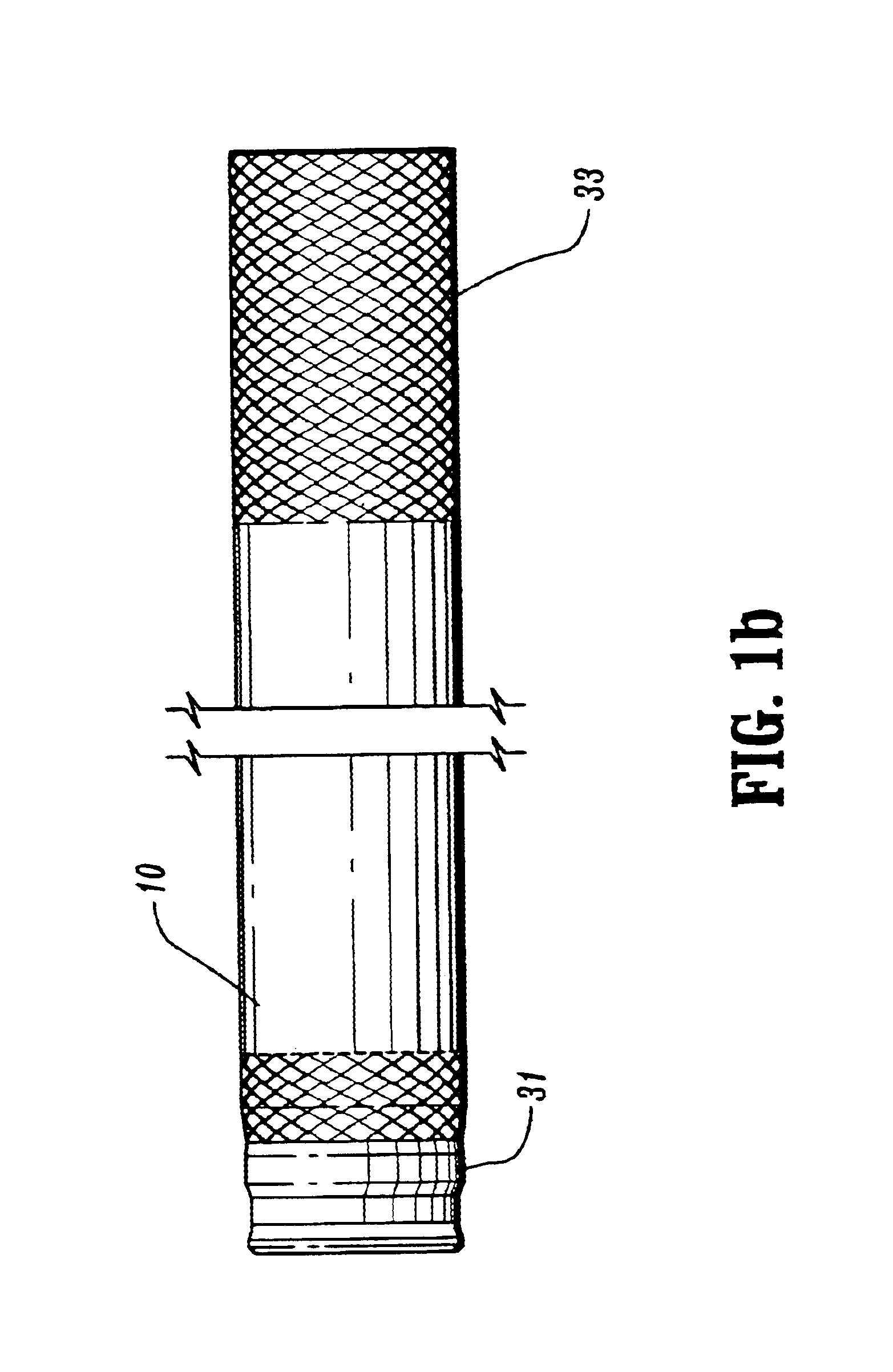
With reference now to the drawings and particularly to FIGS. 1A, 1B, 1C, 2A and 2B, an electronic thermometer is shown configured according to at least one embodiment of the present invention. A probe shaft 10 is shown having a distal end 31 and a proximate end 33 and having a separator 13 disposed on its distal end. In an exemplary embodiment the probe shaft 10 is made from CELCON M90 available from Adam Spence Corporation. Celcon is an acetal that was selected for toughness and notch resistance. Celcon has the additional advantage for the probe shaft material because it can also be extruded. The separator 13 is made from 3033-H14 aluminum. The aluminum material was selected for the separator because aluminum is best suited for the separator fabrication stamping operation. A heater element 12 is in contact with the separator 13 and provides heat thereto. In an exemplary embodiment, the heater element is a 100 ohm, ⅙ watt 1% 0603 SMD resistor. Many resistor configurations will work ...


PUM

PropertyMeasurementUnit
temperatureaaaaaaaaaa
lengthaaaaaaaaaa
temperatureaaaaaaaaaa

Abstract

A prediction type electronic thermometer having an actively controlled heater element thermally isolating the probe tip from the probe shaft. Rapid and accurate temperature measurements are made using predictive algorithms. Control circuitry reads input from the temperature sensing element to compute best heater control signals so that the temperature of the probe shaft rapidly follows changes in the temperature of the probe tip. Thermal isolation between probe shaft and tip impedes heat flow from the heater element to the tip providing more accurate measurements. Rapid and accurate management of shaft temperature allows heat from the patient being measured to be most efficiently transmitted to the temperature sensor element resulting in very fast temperature measurements.

Description

FIELD OF THE INVENTIONThe invention pertains to the field of electronic thermometers and more particularly the field of fast response electronic thermometers employing a sensor probe.BACKGROUND OF THE INVENTIONElectronic thermometers are widely used in the healthcare field for measuring patient's body temperature. Typical electronic thermometers have the form of a probe with an elongated shaft portion. Electronic temperature sensors such as thermistors or other temperature sensitive elements are contained within the shaft portion. Additional electronics connected to the electronic sensor components may be contained within a base unit connected by wire to the shaft portion or may be contained within a handle of the shaft portion, for example. Electronic components receive input from the sensor components to compute the patient's temperature. The temperature is then typically displayed on a visual output device such as a seven segment numerical display device. Additional features of k...

Claims


Application Information

Patent Timeline
Patent Type & Authority Patents(United States)
IPC IPC(8): G01K7/42G01K7/00
CPCG01K7/42
Inventor LANTZ, LORENGAINES, ROBERT B.
Owner CARDINAL HEALTH IRELAND UNLTD
Why Eureka
Try Eureka