Methods and apparatus for cleaning optical connectors
a technology of optical connectors and cleaning methods, applied in the direction of carpet cleaners, cleaning using liquids, instruments, etc., can solve the problems of requiring additional user intervention, affecting the cleaning effect of optical connectors, and the application approach of pad pads is not well suited to cleaning optical connectors with shutters, so as to reduce the amount of dust attracted, reduce the amount of moisture condensation, and facilitate the dislodging of contaminating particles
- Summary
- Abstract
- Description
- Claims
- Application Information
AI Technical Summary
Benefits of technology
Problems solved by technology
Method used
Image

Examples
Embodiment Construction
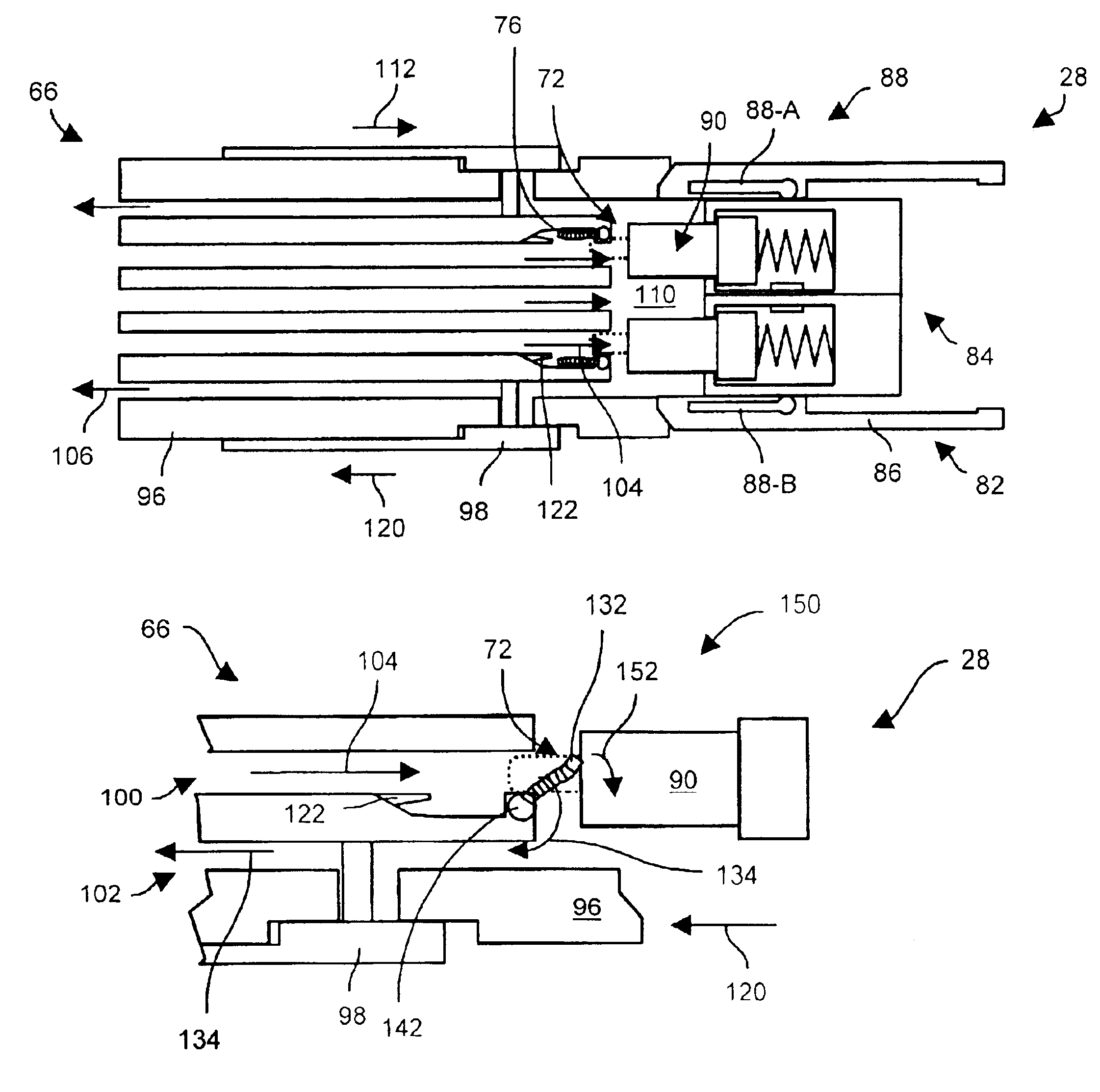
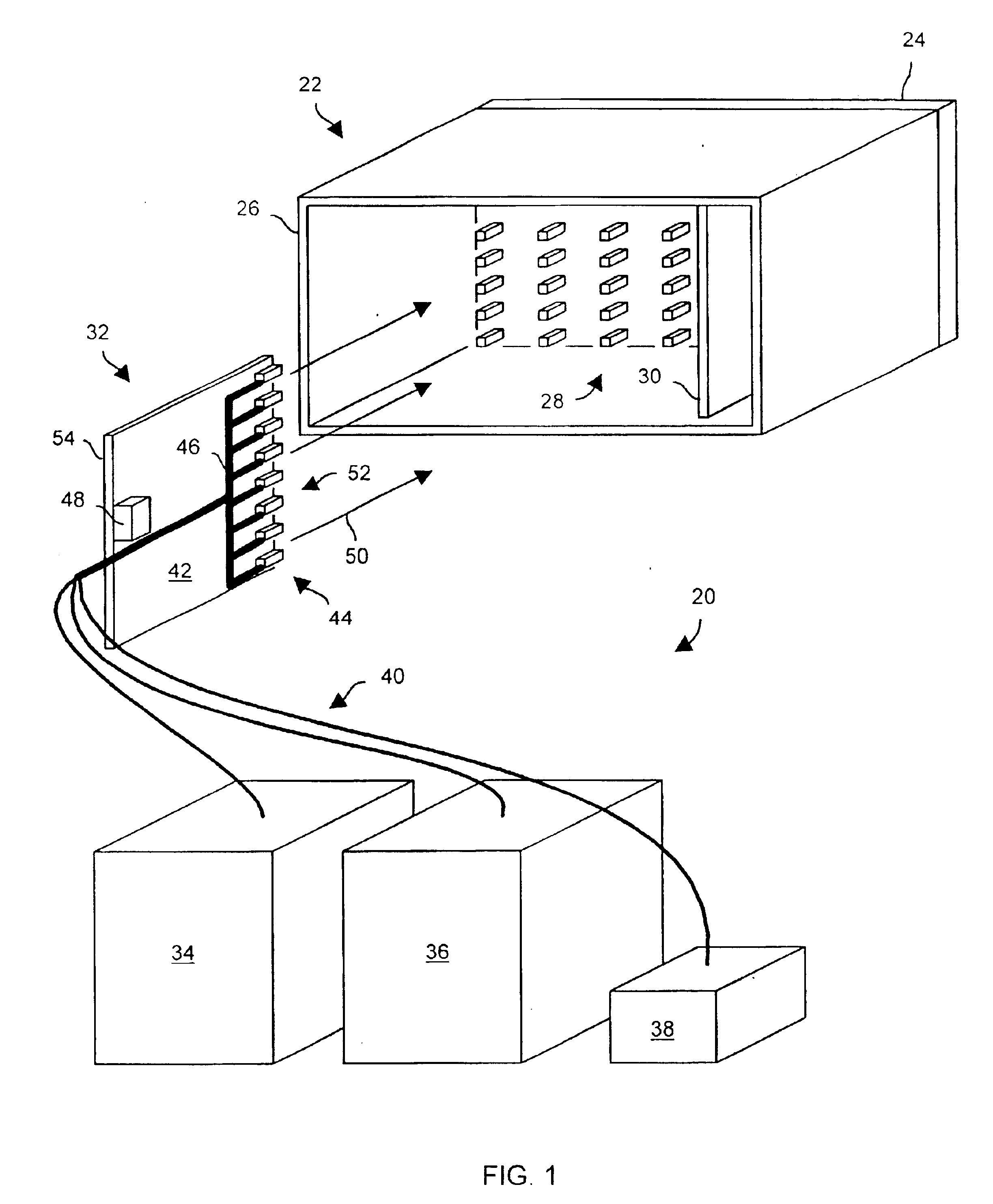
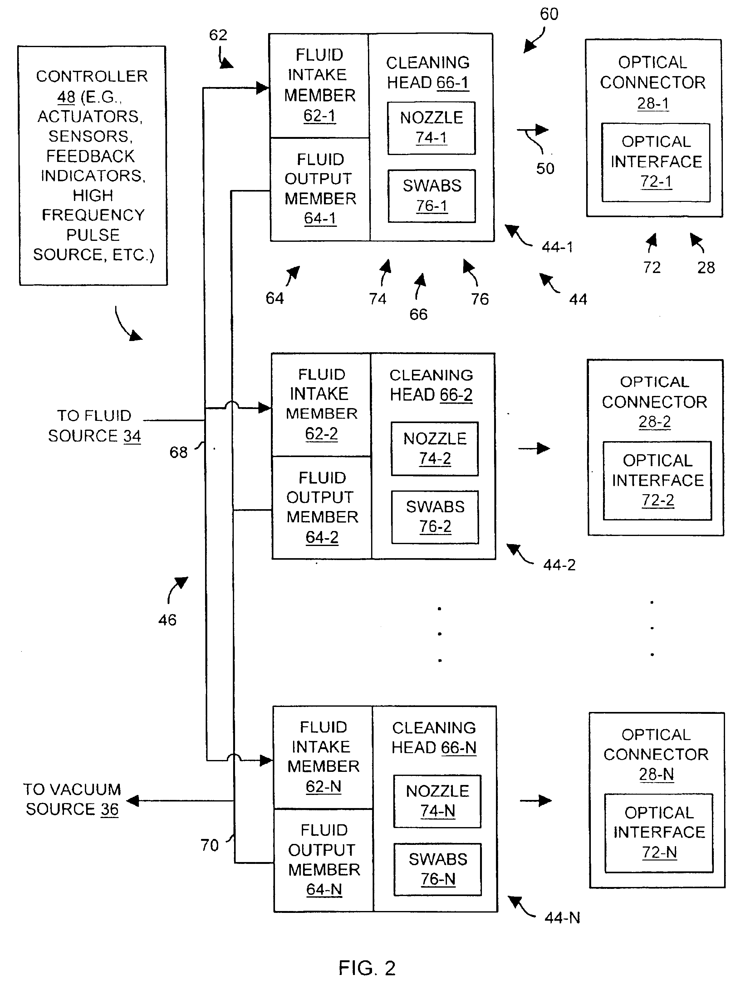
The invention is directed to techniques for cleaning an optical connector which involves directing fluid toward an optical interface of the optical connector through a cleaning head, and drawing the directed fluid away from the optical interface of the optical connector and toward the cleaning head. The directed fluid (e.g., gas) is well-suited for dislodging contaminants such as large particles, small particles and oils. Additionally, since the fluid is drawn away from the optical interface toward the cleaning head, there is little opportunity for these contaminants to fall back over the optical interface to cause recontamination. Furthermore, the use of environmentally safe gases (e.g., carbon dioxide, nitrogen, air, etc.), as the fluid, is clean and manageable. That is, such gases are easy to handle and to direct over and around various parts of the connector for enhanced cleaning (e.g., for cleaning any shutters, for cleaning around any guide pins, for cleaning the optical inter...
PUM
 Abstract
Description
Claims
Application Information
 - Generate Ideas
- Intellectual Property
- Life Sciences
- Materials
- Tech Scout
- Unparalleled Data Quality
- Higher Quality Content
- 60% Fewer Hallucinations
Browse by: Latest US Patents, China's latest patents, Technical Efficacy Thesaurus, Application Domain, Technology Topic, Popular Technical Reports.
© 2025 PatSnap. All rights reserved.Legal|Privacy policy|Modern Slavery Act Transparency Statement|Sitemap|About US| Contact US: help@patsnap.com