
Turbidity sensor

a technology of turbidity sensor and sensor body, which is applied in the field of optical methods and apparatus for measuring turbidity of liquids, can solve the problems of not being able to measure turbidity in-situ, measuring low turbidity of natural water of rivers, lakes and reservoirs, etc., and achieves the effects of reducing the size of the sensor body, high sensitivity and small siz

Inactive Publication Date: 2005-01-11
ECOLAB USA INC
View PDF10 Cites 33 Cited by
  • Summary
  • Abstract
  • Description
  • Claims
  • Application Information

AI Technical Summary

Benefits of technology

It is another object of the present invention to improve a turbidity sensor with a smaller size that may be integrated into a housing already comprising other sensors.
It is another object of the present invention to improve the performance of a turbidity sensor with a design measuring the scattered radiation at the wavelength 860 nm with bandwidth 60 nm as required by the International Standard ISO 7027 “Water Quality—Determination of Turbidity”.
It is another object of the present invention to improve a turbidity sensor with a smaller size and may be integrated into a housing already comprising other sensors.
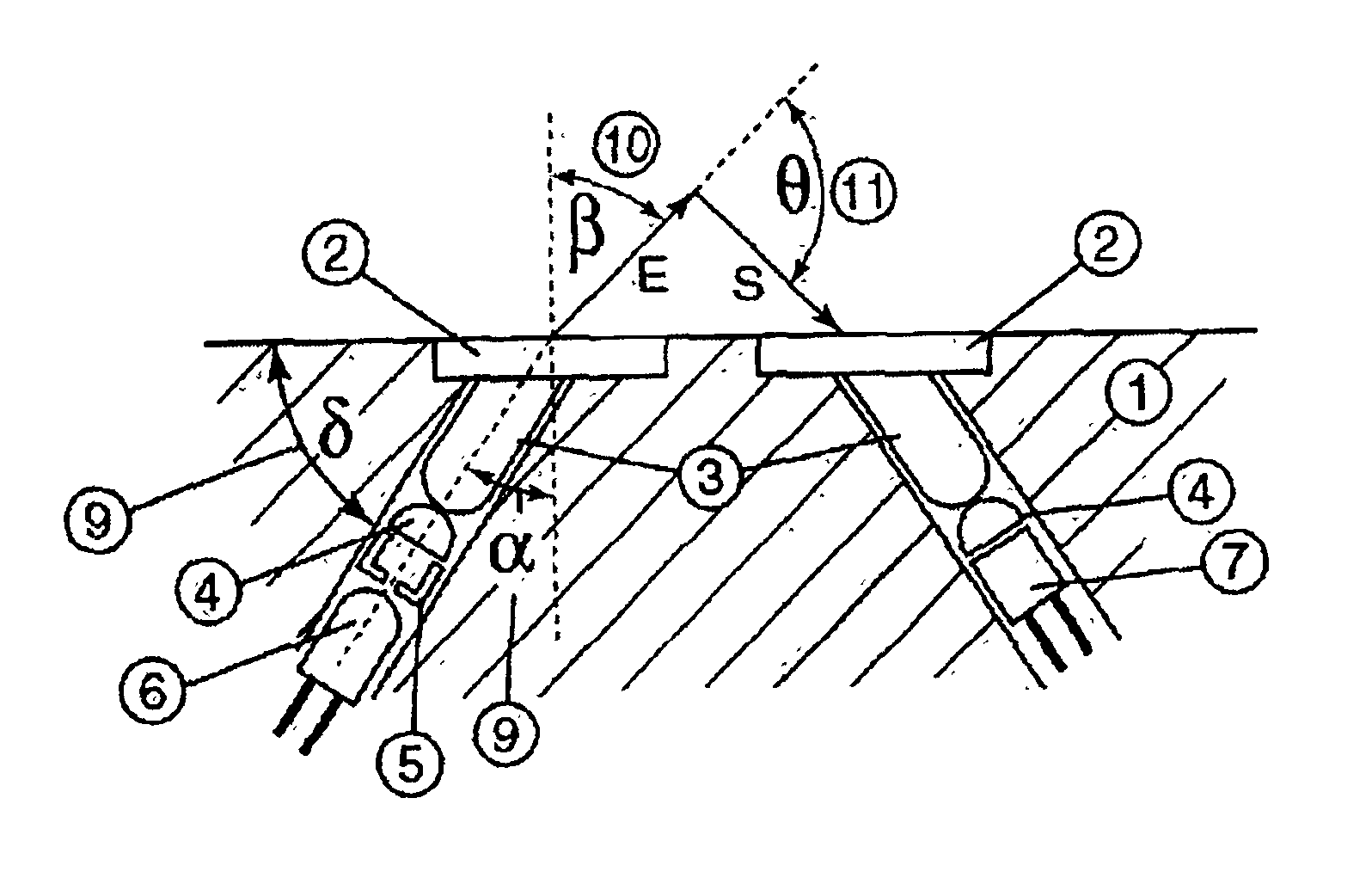
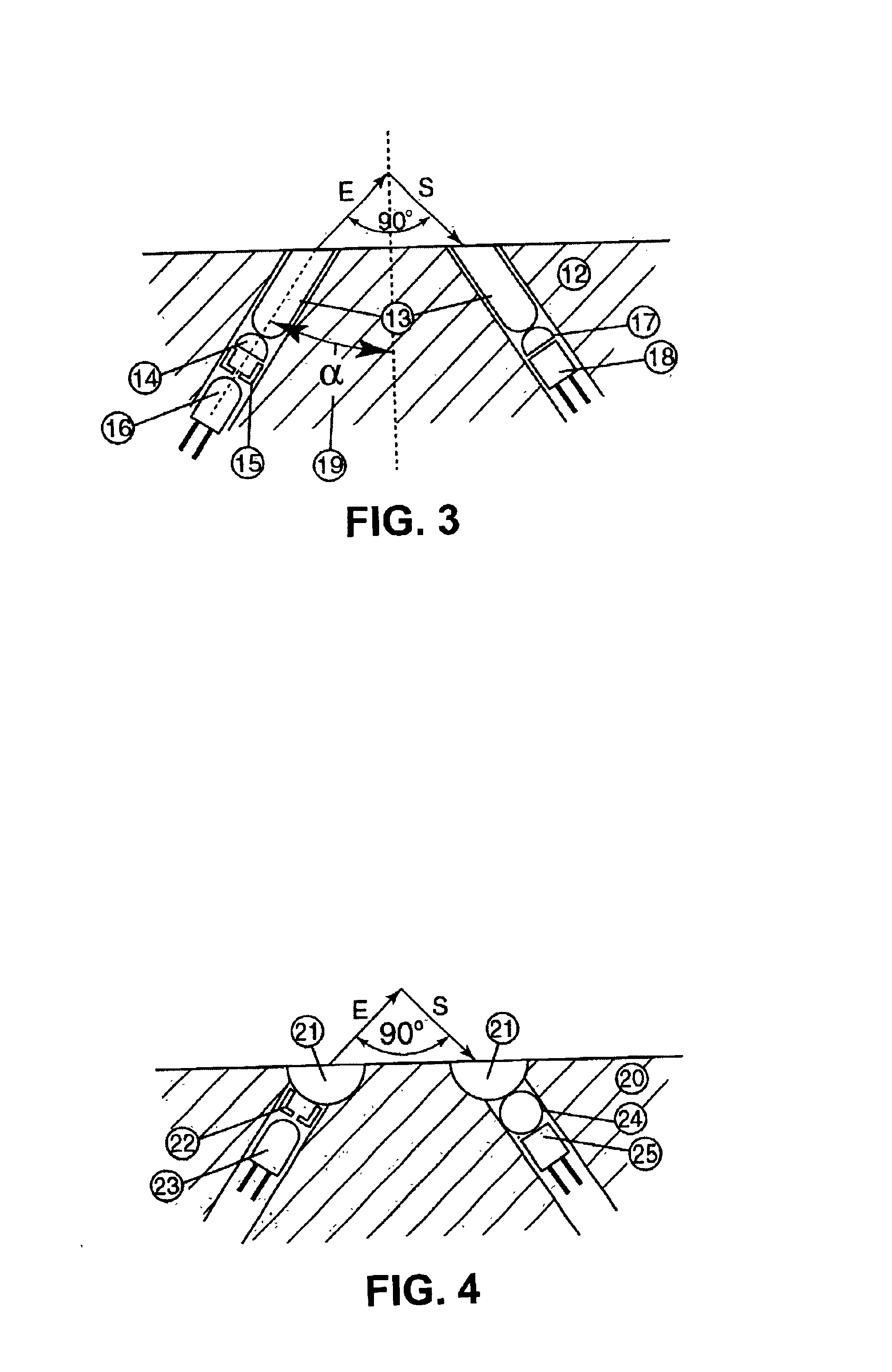
In accordance with the present invention, a turbidity sensor is built with micro focusing devices that allow for decreasing the size of the sensor body while achieving high sensitivity due to higher intensity of excitation light in the analytical area. The turbidity sensor with micro focusing devices has a smaller size and may be integrated into a housing already occupied by other sensors. The turbidity sensor according to the present invention uses lenses with diameter 3.9 mm. An optical assembly of the turbidity sensor has dimensions 20 mm ×15 mm×8 mm. The electronic board for this sensor has size 10 mm×50 mm. The turbidity sensor with micro focusing devices has better signal to noise ratio and may operate with the light emitting diode(s) and photodiode(s) placed directly near the micro focusing devices or alternatively with the light emitting diode(s) and photodiode(s) placed inside the housing using optic fibers of a small diameter to couple the light emitting diode(s) and photodiode(s) with the micro focusing devices. This turbidity sensor with micro focusing devices results in an optical design, which is closer to the requirements of the International Standard ISO 7027. Micro focusing devices, according to the present invention, include prismatic members to compensate difference in refractive indexes of water and glass or plastic parts used for light collimating.

Problems solved by technology

This sensor operates by measuring transmission light but not scattering light such that it cannot measure low turbidities of natural water of rivers, lakes and reservoirs.
However, they require special test cells or covers, and they cannot measure turbidity in-situ.

Method used


Image

  • Turbidity sensor
  • Turbidity sensor
  • Turbidity sensor

Examples


Embodiment Construction

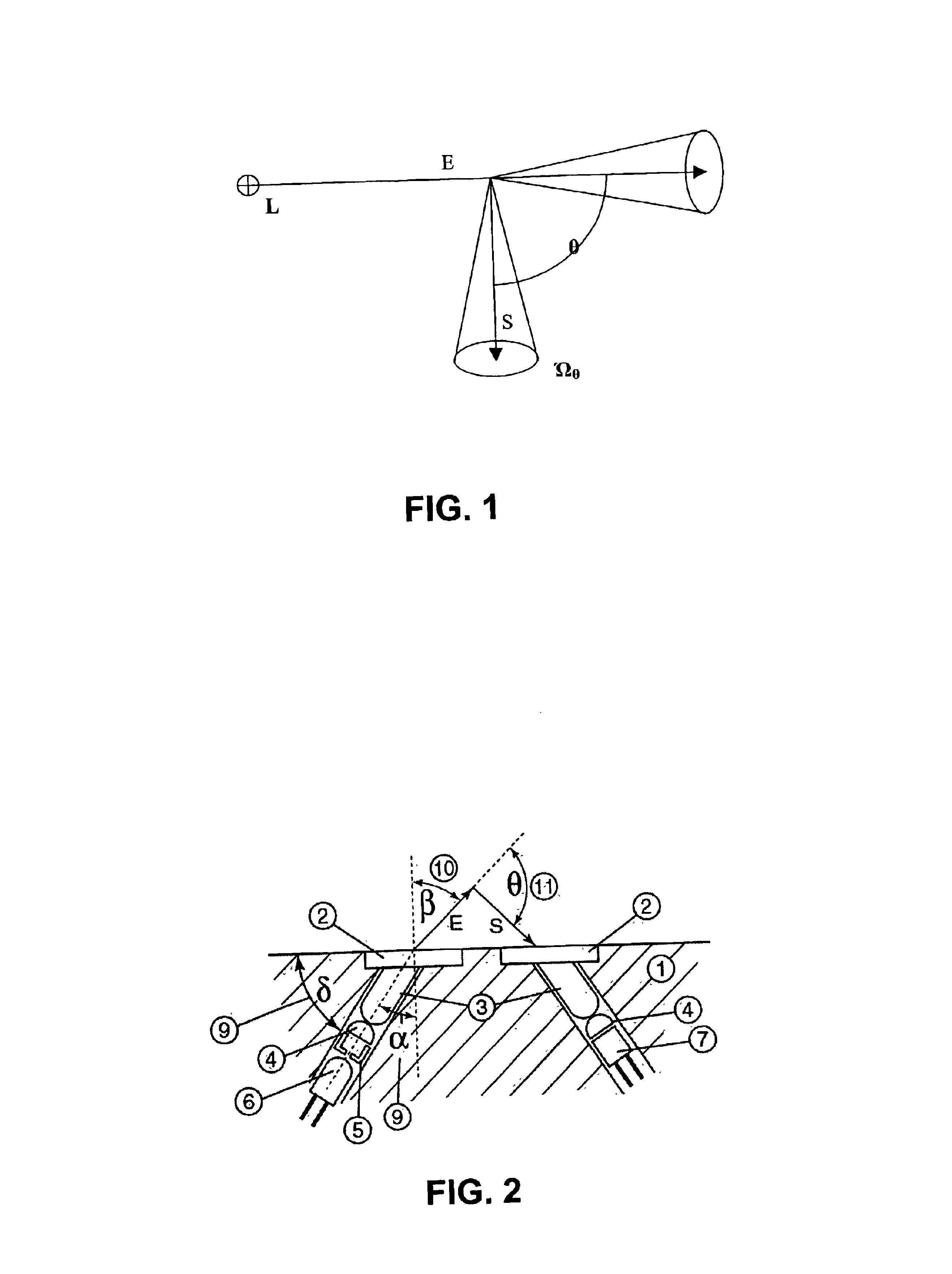
According the ISO 7027, the turbidity should be measured by measuring the scattered radiation at the wavelength 860 nm with bandwidth 60 nm. Referring to the FIG. 1, the optical configuration for the turbidity measurements by measuring diffused radiation (ISO 7027). In FIG. 1, L represents a light source to produce incident radiation with no divergence, E represents the direction of a excitation beam, S represents the direction of a scattered radiation, .theta. represents the measuring angle between the optical axis of the incident radiation and mat of the diffused radiation, and .OMEGA . . . sub.0 represents the aperture angle in the water sample. The light source L produces an infrared beam with no divergence and convergence should be not more than 1.5 degrees. The measuring angle .theta. between the optical axis of the incident radiation and the mat of the diffused radiation should be 90±2.5 degrees. The aperture angle .OMEGA . . . sub.0 in the water sample should be between 20 d...


PUM


Abstract

A small size turbidity sensor for underwater in-situ measurements in the wide range of turbidity values is disclosed that may be integrated into a housing with other underwater sensors. The turbidity sensor incorporates micro focusing devices and light stop that gives no divergence excitation beam with convergence less than 1.5 degrees and the measuring angle between the optical axis of the incident radiation and mat of the diffused radiation 90 ±2.5 degrees. Another embodiment includes internal and external optical calibrators that allows the sensor to work longer without human intervention.

Description

BACKGROUND OF THE INVENTION1. Field of the InventionThe invention relates generally to optical methods and apparatus for measuring turbidity of liquids and more particularly to methods and devices for the in-situ measurement turbidity of the natural water.2. Description of Related ArtsTurbidity sensing provides a quick, practical indication of the relative amount of suspended solids in water or suspended liquids. Many industrial and commercial bath applications can make use of integrated turbidity and conductivity sensing to improve product quality, minimize ingredient consumption, and reduce wastewater discharge. However, the inventors focused on in-situ measurement turbidity of the natural water for environmental monitoring.U.S. Pat. No. 5,589,935 describes turbidity sensor with the capability of regulating the intensity of a light source. This sensor operates by measuring transmission light but not scattering light such that it cannot measure low turbidities of natural water of r...

Claims


Application Information

Patent Timeline
IPC IPC(8): G01N21/53G01N21/47
CPCG01N21/53G01N2201/0639
Inventor TOKHTUEV, EUGENEOWEN, CHRISTOPHERSKIRDA, ANATOLYSLOBODYAN, VIKTORGOIN, JOSE
Owner ECOLAB USA INC
Learn More