
Electrotransport delivery device with voltage boosting circuit

a technology of voltage boosting circuit and electrotransport delivery device, which is applied in the field of electrotransport, can solve the problems of limiting the wider application of this valuable technique, the size and cost of electrotransport delivery device, and the limitation of the application

Inactive Publication Date: 2005-01-11
ALZA CORP
View PDF76 Cites 45 Cited by
  • Summary
  • Abstract
  • Description
  • Claims
  • Application Information

AI Technical Summary

Benefits of technology

It is an aspect of the present invention to provide a method of operating with increased efficiency an electrotransport agent delivery device having a voltage boosting circuit.
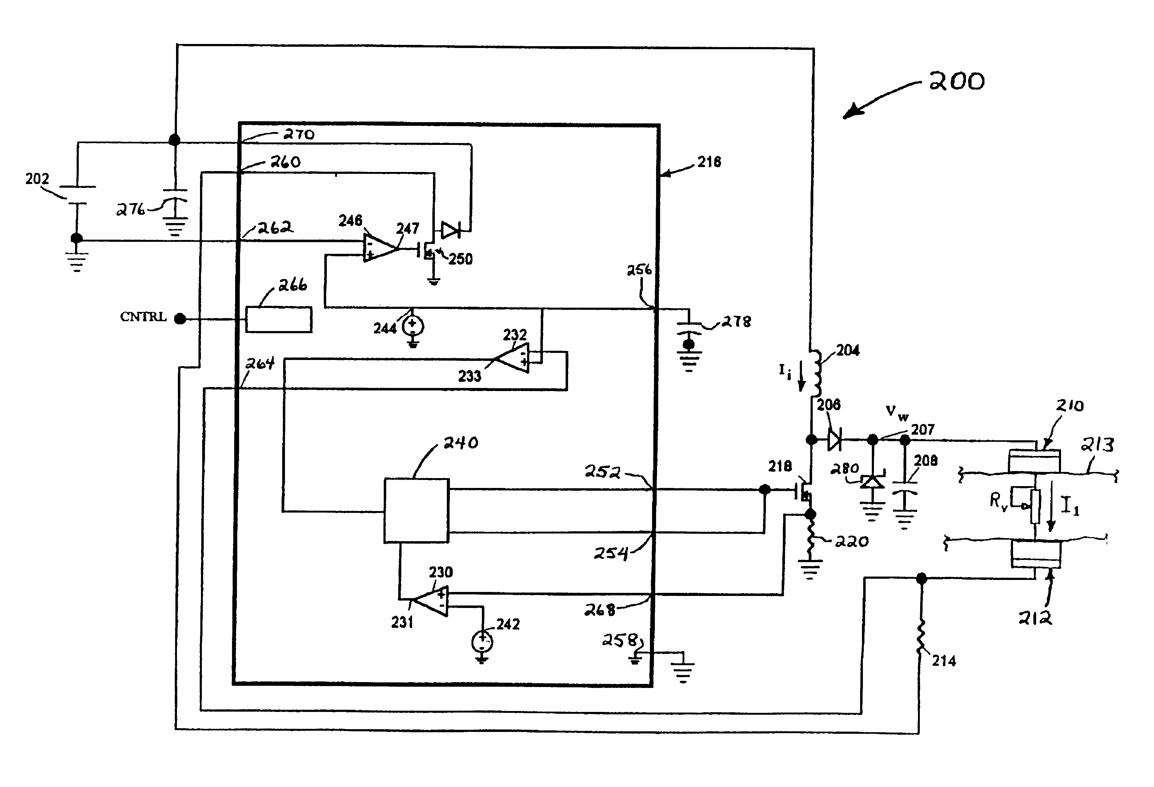
The present invention provides a method for operating an electrotransport agent delivery device having a voltage boosting circuit which boosts the power supply (eg, battery) output voltage, in which boosting circuit the boost multiple is automatically controlled in response to the skin resistance of the patient. The device is adapted to deliver a therapeutic agent through an animal body surface (eg, human skin) by electrotransport. The device has a source of electrical power (eg, one or more batteries) with an output voltage. The power source output voltage is boosted with a voltage booster having an adjustable boost multiple to provide a working voltage. A body surface parameter selected from the electrical resistance of the body surface, the voltage drop across the body surface and / or the current applied through the body surface is sensed and the boost multiple is adjusted based upon the sensed body surface parameter to achieve an adjusted working voltage. By adjusting the boost multiple based upon the sensed body parameter (eg, skin resistance), the device applies only that level of voltage which is needed to deliver a predetermined level of electrotransport current, without excess voltage being consumed by the boost circuit. Thus, the method of the present invention provides increased efficiency in the operation of an electrotransport delivery device.

Problems solved by technology

Nevertheless, some limitations still remain, restricting the wider application of this valuable technique.
One such limitation is the size and cost of electrotransport delivery devices.
In particular, the batteries needed to power electrotransport devices comprise a significant contribution to the overall size and weight, as well as the cost, of these smaller, patient-worn electrotransport delivery devices.
The problem of reducing the cost of the power supply for an electrotransport delivery device is complicated by the fact that the electrical resistance of the patient body surface (eg, skin) is not constant during electrotransport delivery.
Although conventional voltage boosting circuits can supply the output voltage necessary to accommodate the high initial skin resistance, they reduce the efficiency of the apparatus and require more battery output voltage during periods when the skin resistance is lower than the initial state, resulting in lower efficiency and increased battery size and costs.
One disadvantage of the Jacobsen circuit is that the peak value of the fixed and multiplied voltage appears directly across the electrodes.
The peak voltage is unnecessary for conditions where the skin resistance is low, and results in unnecessarily high current pulses of therapeutic current and possible adverse effects on the skin.

Method used


Image

  • Electrotransport delivery device with voltage boosting circuit
  • Electrotransport delivery device with voltage boosting circuit
  • Electrotransport delivery device with voltage boosting circuit

Examples


Embodiment Construction

It is an aspect of the present invention to provide a method of operating with increased efficiency an electrotransport agent delivery device having a voltage boosting circuit.

It is another aspect of the present invention to provide a method of operating an electrotransport agent delivery device in which the power supply voltage is boosted to a level which is optimally suited to the conditions (eg, skin resistance) of agent delivery.

The present invention provides a method for operating an electrotransport agent delivery device having a voltage boosting circuit which boosts the power supply (eg, battery) output voltage, in which boosting circuit the boost multiple is automatically controlled in response to the skin resistance of the patient. The device is adapted to deliver a therapeutic agent through an animal body surface (eg, human skin) by electrotransport. The device has a source of electrical power (eg, one or more batteries) with an output voltage. The power source output volt...


PUM


Abstract

An electrotransport device (10) for delivering therapeutic agents includes and adjustable voltage boost multiple controller (100, 200) for boosting the voltage from a power source (102, 202) to a working voltage VW having a value just sufficient to provide the desired therapeutic current level II through the electrodes (108, 112), at least of which contains the therapeutic agent to be delivered.

Description

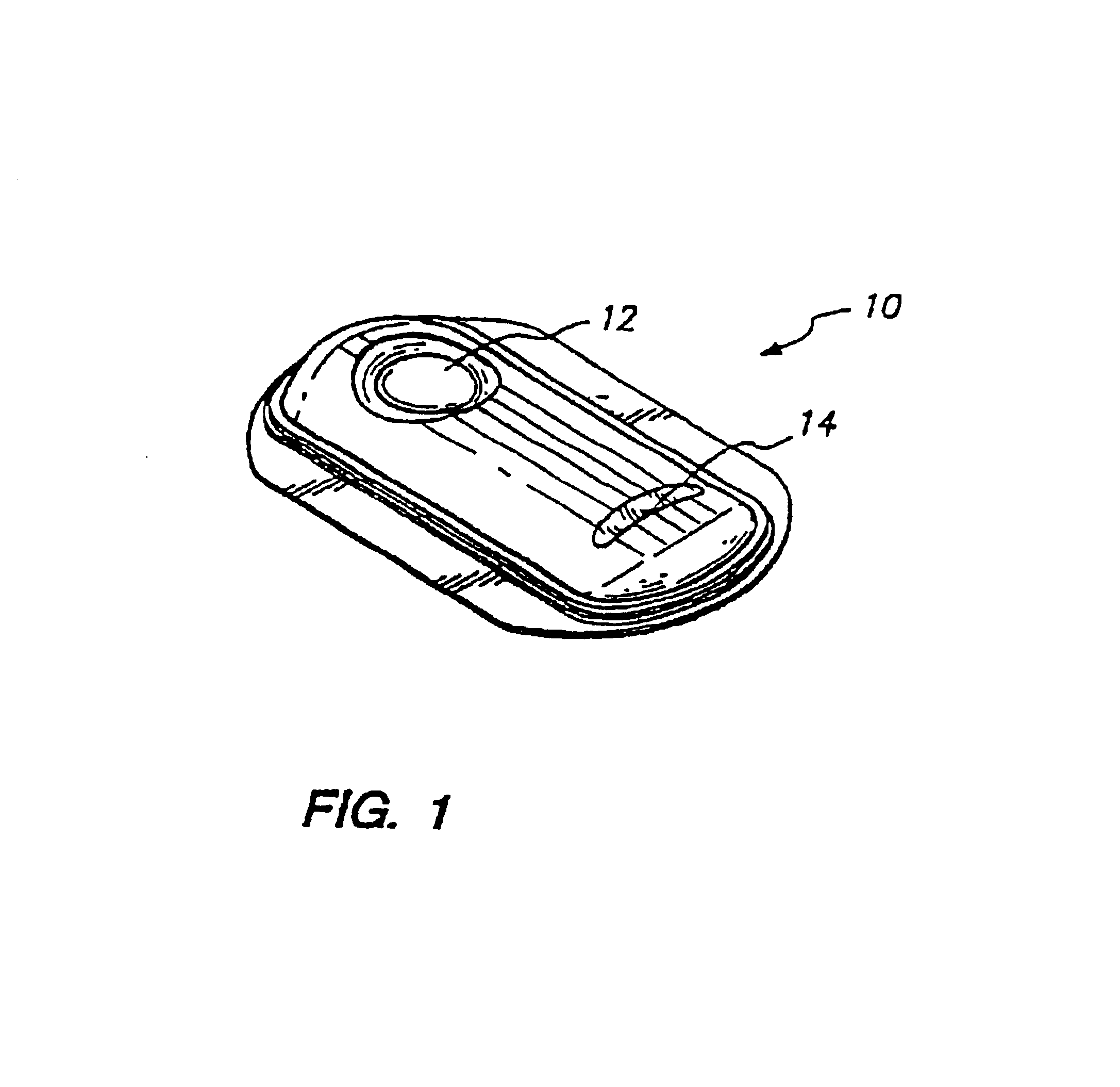
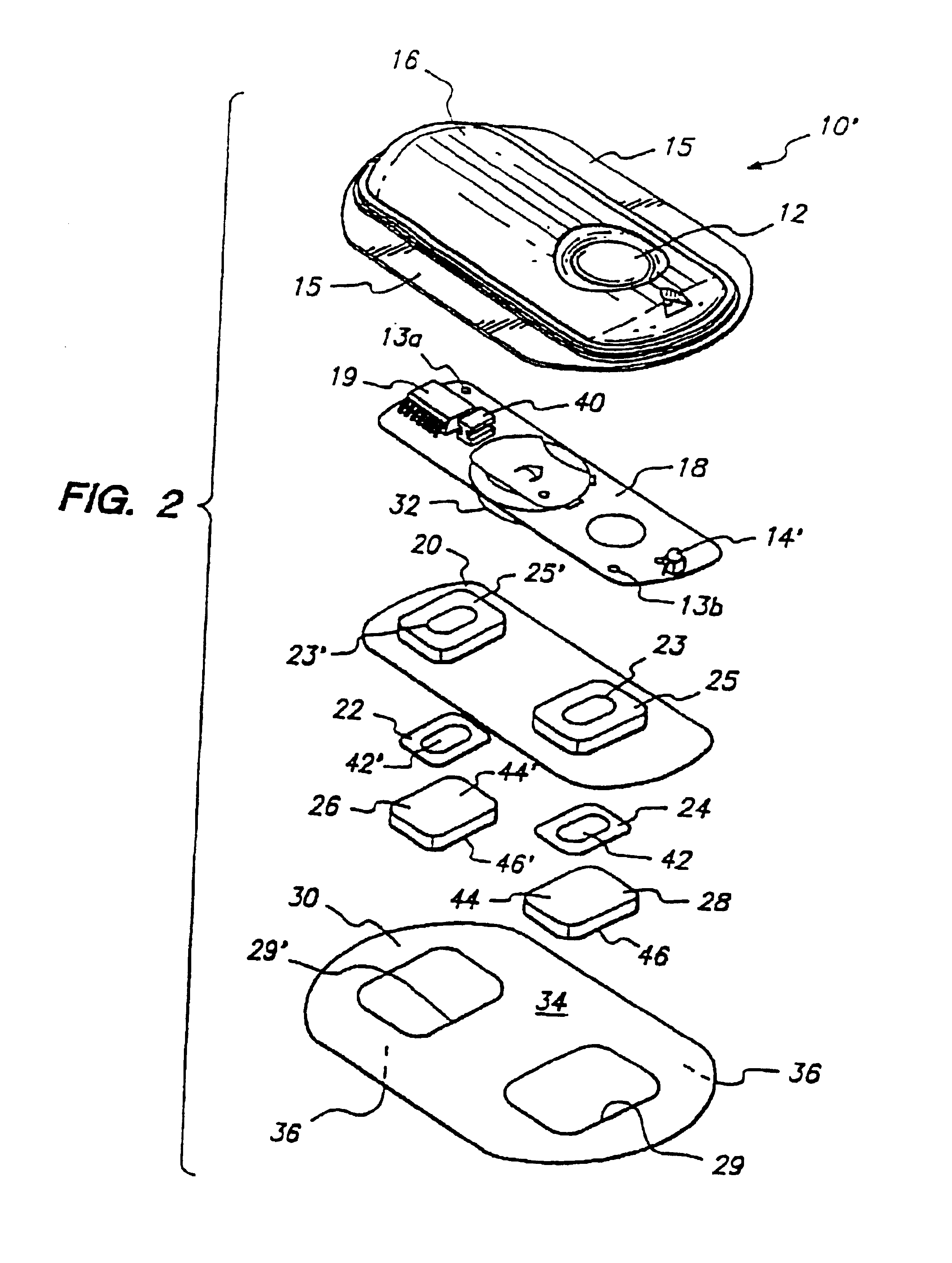
This invention relates to an electrotransport device for transdermally or transmucosally delivering a beneficial agent leg, a drug) to a patient. More particularly, the invention relates to a portable or patient-worn electrotransport delivery device having an improved power supply.BACKGROUND ARTThe term “electrotransport” as used herein refers generally to the delivery of an agent (eg, a drug) through a membrane, such as skin, mucous membrane, or nails, which delivery is induced or aided by the application of an electric potential. For example, a beneficial therapeutic agent may be introduced into the systemic circulation of an animal (eg, a human) by electrotransport delivery through the skin.The electrotransport process has been found to be useful in the transdermal administration of drugs including lidocaine hydrochloride, hydrocortisone, fluoride, penicillin, dexamethasone sodium phosphate, and many other drugs. Perhaps the most common use of electrotransport is in diagnosing cy...

Claims


Application Information

Patent Timeline
Patent Type & Authority Patents(United States)
IPC IPC(8): A61N1/32A61N1/30
CPCA61N1/044A61N1/325A61N1/30A61N1/0448
Inventor RIDDLE, THOMAS A.MCNICHOLS, LARRY A.BADZINSKI, JOHN D.
Owner ALZA CORP
Learn More